










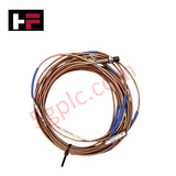
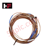
Product Details
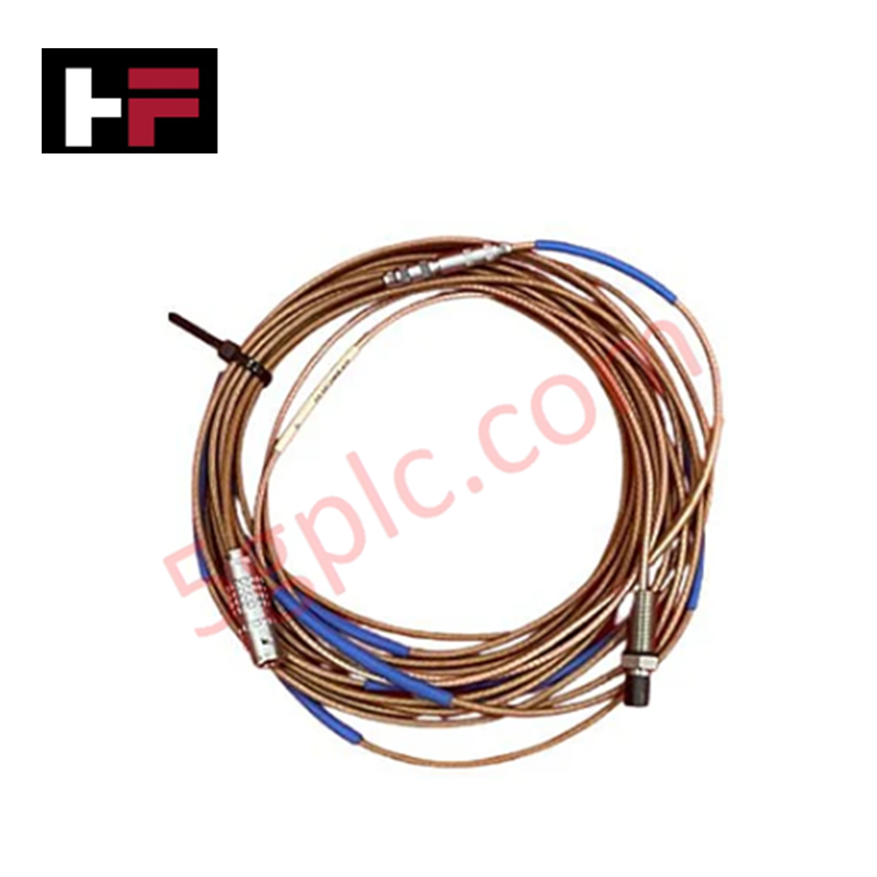
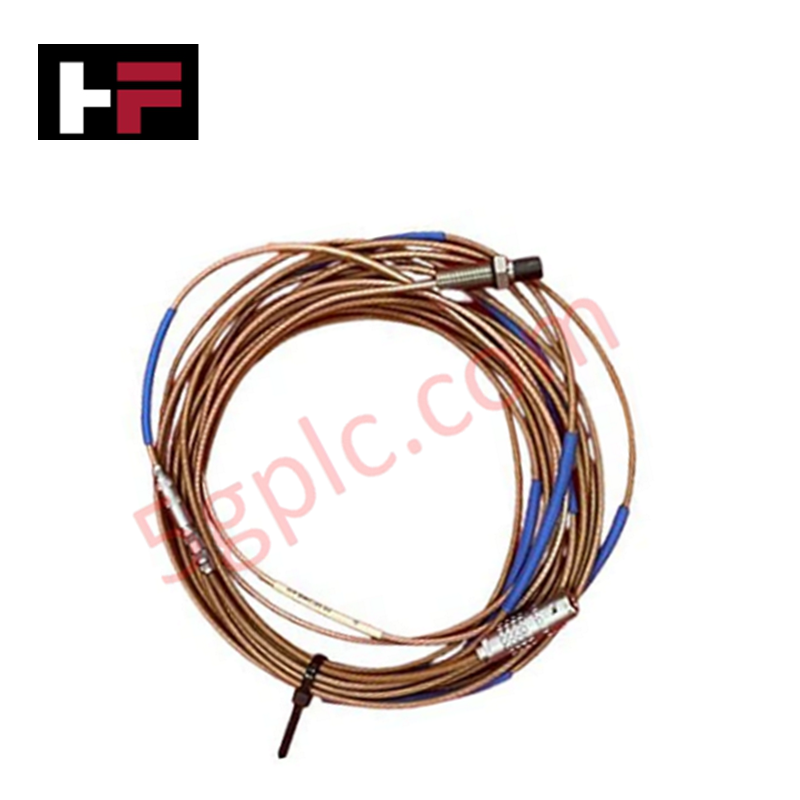
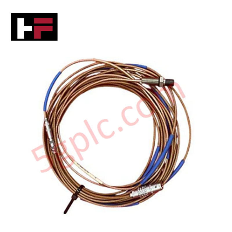
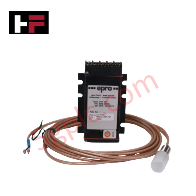
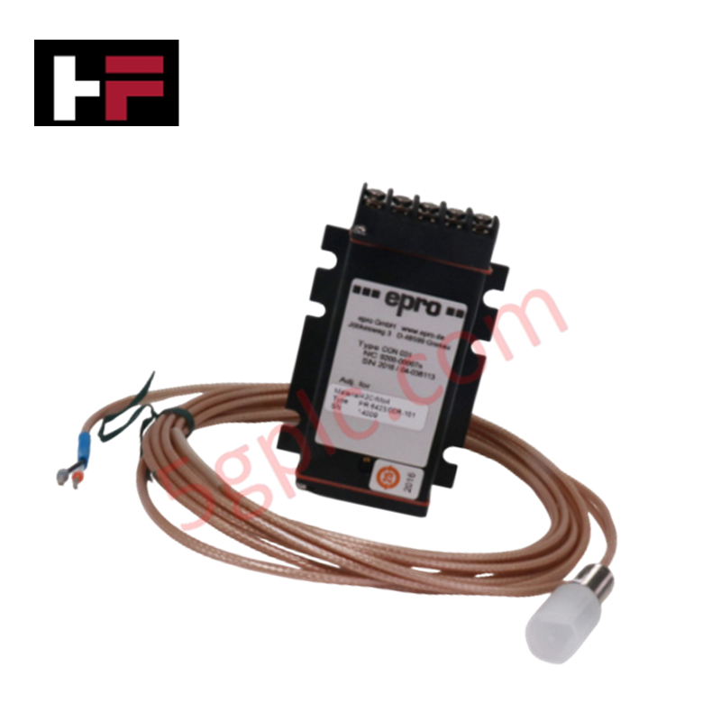
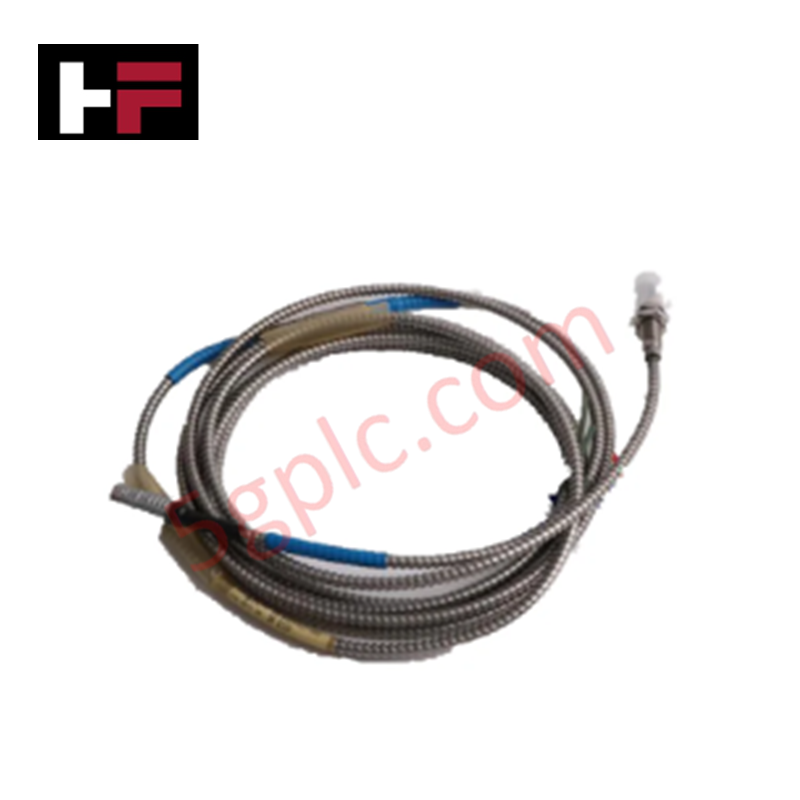
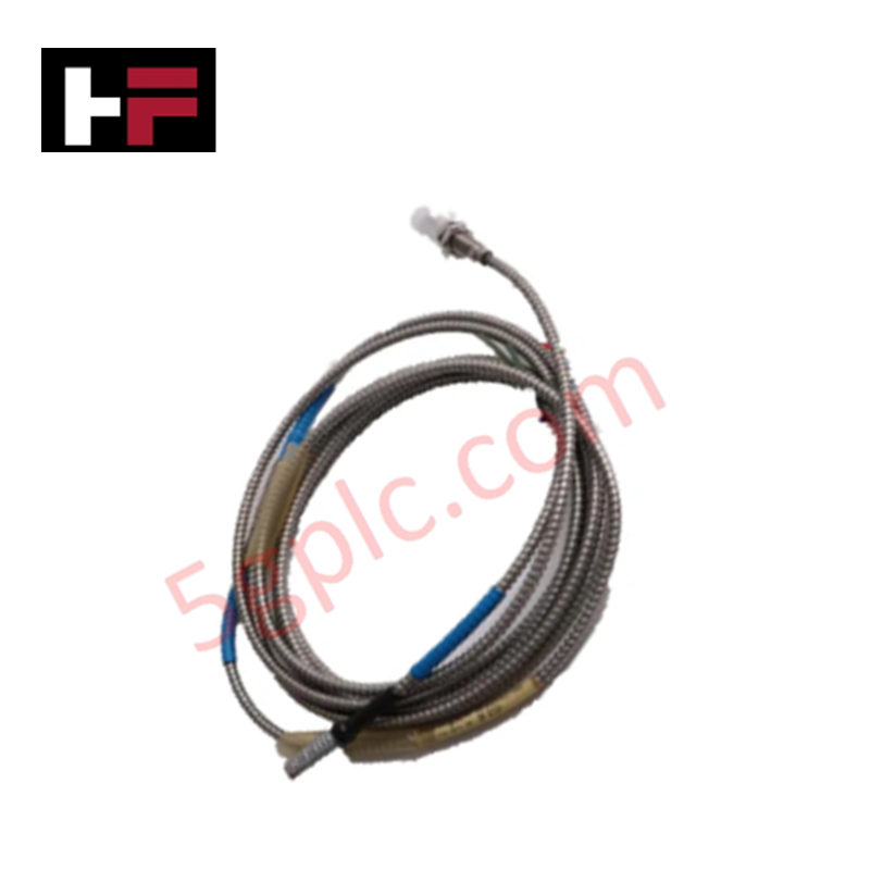
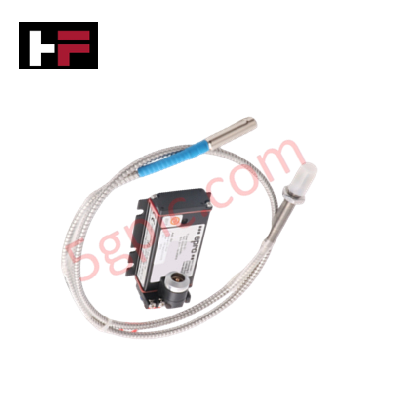
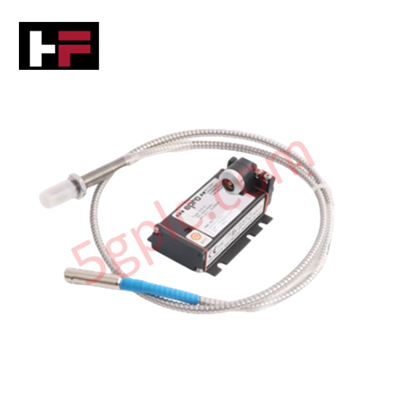
The Emerson PR6423/010-120-CN, also cataloged as the PR6423 Proximity Sensors, operates as a dedicated hardware component for non-contact shaft displacement and dynamic vibration measurement within Emerson and EPRO machinery monitoring platforms. The transducer assembly establishes an eddy current inductive field at the probe tip to convert physical gap variations relative to conductive metal targets into continuous electrical outputs without mechanical contact.
Hardware Specifications
| Parameter | Specification |
|---|---|
| Model | PR6423/010-120-CN |
| Brand | Emerson |
| Origin | United States |
| Operating Temp | -35 to +180 deg C (Sensor Head) |
| Power Consumption | Standard loop power dissipation |
| Probe Head Diameter | 8 mm |
| Measurement Principle | Non-contact Eddy Current |
| Target Material | Ferromagnetic steel |
| Housing Material | Stainless steel (SST) |
| Cable Interface | Armored / Standard extension cable assembly |
4-20 mA HART Loop Protocol & Channel Isolation
When wired into compatible CON series signal converters, the sensor interface delivers conditioned analog voltage or 4-20 mA HART loop protocol outputs to upstream monitoring racks. Galvanic channel-to-channel isolation decouples field sensor signals from system ground references, preventing common-mode earth potential interference in multi-channel installations. Internal thermal compensation preserves scale factor stability across wide operating temperature spans, ensuring accurate peak-to-peak vibration and axial position feedback.
Frequently Asked Questions
Q: What is the purpose of the CN suffix on the PR6423/010-120-CN sensor?
A: The CN suffix designates specific cable length, connector hardware, and terminal configurations tailored for standardized regional control panel installations.
Q: How does the eddy current transducer measure vibration without touching the shaft?
A: The probe coil emits a high-frequency electromagnetic field that induces eddy currents in the metal target, altering field impedance proportionally to physical gap distance.
Field Installation Guidelines
Maintain an unobstructed metallic clearance radius around the 8 mm sensing tip of at least 1.5 times the tip diameter to prevent surrounding enclosure geometry from inducing false inductance loading. Route sensor cabling inside dedicated grounded metallic conduit, maintaining physical separation from high-voltage AC cables and motor drives. Connect the cable shield braid to the technical earth terminal frame at a single point only to avoid circulating ground loop currents. Secure mounting locknuts to standard torque specifications and protect exposed connections with self-amalgamating tape.
Additional Information
- 100% Genuine Parts: All products are original and authentic, ensuring reliable industrial performance.
- 30-Day Refund Guarantee: Return any in-stock item within 30 days in original, unopened packaging for a full refund (excluding shipping and fees).
- 12-Month Warranty: Covers defects in materials or workmanship; excludes misuse, normal wear, or unauthorized modifications.
- Worldwide Shipping: We ship via USPS, UPS, FedEx, and DHL. Delivery times vary by country and may be subject to customs or import fees.
- Support & Contact: Technical and warranty assistance is available anytime. Contact us here: Contact.
- Purchase Guidance: Check product specifications and compatibility carefully before ordering to ensure proper application.




Tech & Buying Guide

Redefining Control Systems: The Rise of Flexible I/O Modules in Industrial Automation
Conventional input-output architectures often limit engineering agility and inflate long-term inventory costs. Today, Flexible Input/Output Modules (FIOM) are transforming how control system engineers design, commission, and maintain automation infrastructure. By allowing individual channel software configuration, FIOM technology bridges the gap between rigid hardware design and dynamic plant requirements.

Understanding Modern SCADA Systems: Architecture, Communication Topologies, and Industrial Applications
Supervisory Control and Data Acquisition (SCADA) systems form the digital backbone of modern industrial automation. They collect critical field data, transmit signals across vast distances, and empower plant operators with real-time process visibility. Across modern infrastructures, SCADA solutions streamline centralized control and maintain continuous operational uptime.

Understanding OPC Servers in Modern Industrial Automation: Principles, Architecture, and Applications
In industrial automation, connecting physical hardware with high-level software remains a primary operational challenge. Factories utilize programmable logic controllers (PLCs), distributed control systems (DCS), human-machine interfaces (HMIs), and smart sensors from diverse vendors. These devices often speak different proprietary protocols. Open Platform Communications (OPC) servers solve this interoperability challenge by standardizing how data flows across factory networks.