










Product Details
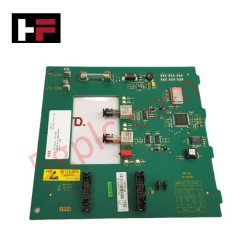
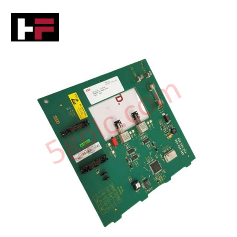
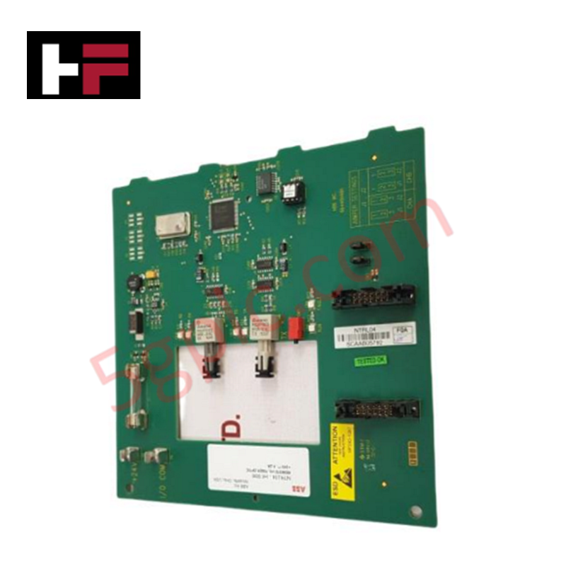
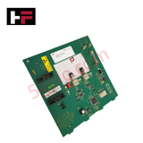
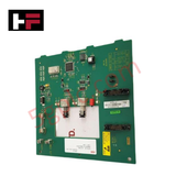
Configured for high-speed signal extension in HNET communication networks, the ABB NTRL04, also cataloged as the NTRL04 Fiber Optic Repeater Termination Unit, provides direct physical/electrical execution.
Hardware Specifications
| Parameter | Specification |
| Model | NTRL04 |
| Brand | ABB |
| Origin | United States / Sweden |
| Weight | 0.45 kg |
| Dimensions | 17.8 cm x 17.8 cm x 2.54 cm |
| Operating Temp | 0 to +60 deg C (Standard industrial parameters) |
| Power Consumption | 90 mA typical, 200 mA maximum |
| Voltage Range | 21.6 VDC minimum, 24 VDC nominal, 28 VDC maximum |
| Network Protocol | HNET |
| HNET Communication Rate | 4 Mbaud |
| Maximum Devices Supported | Up to 12 devices (6 redundant HNET drops) |
| Intra Cabinet Distance | 30 m (electrical) |
| Inter Cabinet Distance | 3,000 m (optical) |
| Fiber Optic Type | Multimode |
| Fiber Optic Size | 62.5/125 um |
| Attenuation | -3.5 dB/km |
| Wavelength | 840 nm |
| Bandwidth | 160 MHz/km |
| Connector Type | ST style with right-angle strain relief |
Backplane Bus Communication Velocity and Deterministic Networks
The hardware design leverages specialized physical layer media conversion to support a constant backplane bus communication velocity across the HNET infrastructure. Operable at a deterministic 4 Mbaud data rate, the transceiver circuits prevent frame jitter and transmission latencies between inter-cabinet nodes. Optical isolation characteristics provide cross-talk suppression and eliminate ground loop potential across the 3,000 m multimode fiber spans. The physical interface handles up to 6 redundant HNET drops without modifying firmware flash configuration parameters or decreasing network throughput.
Frequently Asked Questions
Q: What is the maximum current draw of the module under full load configurations?
A: The module exhibits a typical current draw of 90 mA at 24 VDC. Under peak traffic across all redundant HNET drops, the maximum current draw is rated at 200 mA.
Q: Can the fiber optic connectors accommodate standard straight ST cables?
A: The physical housing layout requires ST style connectors equipped with right-angle strain relief to maintain the specified 2.54 cm depth clearance inside the cabinet enclosure.
Q: What are the cable segment limitations for electrical versus optical links?
A: Electrical routing within a single cabinet or adjacent enclosures is restricted to 30 m. Optical links utilizing 62.5/125 um multimode fiber can extend up to 3,000 m without intermediate signal amplification.
Field Installation Guidelines
-
Mounting Stability: Ensure the termination unit is securely locked onto the mounting structure to prevent mechanical stress on the right-angle ST fiber connectors.
-
Fiber Cable Bend Radius: Adhere to the minimum bend radius specifications for 62.5/125 um multimode fiber cables during routing to avoid localized attenuation spikes exceeding -3.5 dB/km.
-
Power Connection: Verify that input power remains within the 21.6 VDC to 28 VDC boundaries. External inline fusing is recommended to protect the internal DC-DC converter stages.
-
Shielding and Grounding: Electrical HNET drop cables must be properly shielded, with the shield terminated at the designated cabinet ground bus to suppress electromagnetic interference.
Additional Information
- 100% Genuine Parts: All products are original and authentic, ensuring reliable industrial performance.
- 30-Day Refund Guarantee: Return any in-stock item within 30 days in original, unopened packaging for a full refund (excluding shipping and fees).
- 12-Month Warranty: Covers defects in materials or workmanship; excludes misuse, normal wear, or unauthorized modifications.
- Worldwide Shipping: We ship via USPS, UPS, FedEx, and DHL. Delivery times vary by country and may be subject to customs or import fees.
- Support & Contact: Technical and warranty assistance is available anytime. Contact us here: Contact.
- Purchase Guidance: Check product specifications and compatibility carefully before ordering to ensure proper application.









Tech & Buying Guide

Mastering the Siemens PLC Scan Cycle: How the CPU Executes Automation Programs
Industrial automation relies heavily on programmable logic controllers (PLCs) to manage complex manufacturing processes. Many engineers dive straight into programming without mastering the underlying architecture. However, understanding how a PLC CPU executes a program ensures reliable system design. Therefore, mastering the scan cycle optimizes both performance and troubleshooting in modern control systems.

How to Connect to Siemens S7 PLCs: 5 Essential Communication Methods
Establishing a reliable hardware link between a programming terminal and a Siemens SIMATIC controller is essential for engineering workflows. Field engineers rely on distinct physical layers, ranging from legacy serial connections to high-speed Industrial Ethernet protocols. Modern factory automation environments prioritize fast data transfer and seamless driver integration. Selecting the correct connection method simplifies program downloads, online monitoring, and system troubleshooting in complex control systems.

Will PLCs Become Obsolete? The Future of Control Systems in Industry 4.0
Modern manufacturing is undergoing a rapid technological transformation driven by Industry 4.0 innovations. Technologies like Artificial Intelligence (AI), Machine Learning (ML), and the Industrial Internet of Things (IIoT) are dominating discussions across the factory automation sector. Consequently, many engineers wonder if these advanced digital tools will eventually replace traditional Programmable Logic Controllers (PLCs). However, evaluating the core physics of industrial operations reveals a very different reality for control systems.