












Product Details
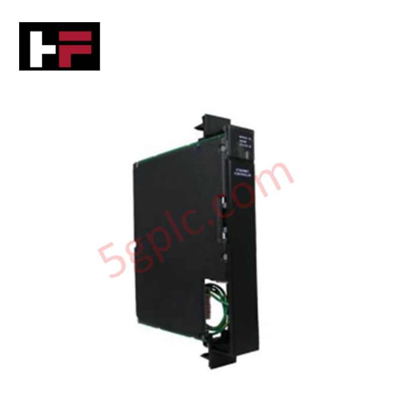
The GE MVC3013-4001, also cataloged as the MVC3013 Mains Voltage Monitoring Device, operates as a dedicated hardware component for continuous line voltage tracking and power quality signal processing within 3-phase 480 VAC power systems.
Hardware Specifications
| Parameter | Specification |
|---|---|
| Model | MVC3013-4001 |
| Brand | GE (GE Fanuc) |
| Origin | USA |
| Weight | 0.5 kg |
| Dimensions | 20 cm x 11.5 cm x 5.7 cm |
| Operating Temp | -40 to +70 deg C (-40 to +158 deg F) |
| Power Consumption | Standard internal bus/line powered |
| Voltage Range | 3-phase 480 VAC power systems |
| Measurement Accuracy | +/-2% |
| Communication Protocol | RS-485 Modbus |
| Alarm Functions | User-configurable for overvoltage, undervoltage, and power outages |
Deterministic Communication & Deterministic Processing Integration
The MVC3013-4001 converts high-voltage 3-phase line feeds into digitized network parameters for real-time evaluation across serial architecture bus interfaces. Supporting RS-485 Modbus protocol communication, the module distributes power telemetry and alarm triggers without introducing latency into upstream automation logic.
Designed to maximize backplane bus communication velocity and controller synchronization, the unit maintains high internal sampling rates for rapid overvoltage, undervoltage, and outage detection. Onboard firmware flash compatibility enables persistent retention of user-configured trip thresholds and diagnostic parameters during sustained power outages.
Frequently Asked Questions
Q: What voltage systems and measurement tolerance levels are supported by the MVC3013-4001?
A: The device monitors 3-phase 480 VAC industrial power systems with a measurement accuracy tolerance within +/-2%.
Q: Which communication interface is used to output voltage metrics and diagnostic alarms?
A: Diagnostic data, line voltage metrics, and configurable alarms are transmitted via an RS-485 Modbus serial communication link.
Q: How are alarm parameters managed during power loss events?
A: Configured alarm states for overvoltage, undervoltage, and total power outages are stored in non-volatile memory onboard the module.
Field Installation Guidelines
- Power Isolation: Ensure all 3-phase 480 VAC main feeds and secondary control power sources are de-energized and locked out before wiring or mounting the unit.
- Grounding Safety: Connect an ESD grounding wrist strap to a verified chassis earth ground point prior to handling internal connections or terminal blocks.
- Mechanical Alignment: Fasten the 20 cm x 11.5 cm x 5.7 cm enclosure securely onto the mounting panel or DIN rail structure to prevent vibration-induced loosening.
- Serial Cable Shielding: Route RS-485 Modbus communication wiring in shielded twisted-pair cable separate from 3-phase high-voltage lines, grounding the shield at a single cabinet earth point.
- Terminal Fastening: Verify correct phase sequence termination and torque all terminal block screws to standard panel values before re-energizing the main power line.
Additional Information
- 100% Genuine Parts: All products are original and authentic, ensuring reliable industrial performance.
- 30-Day Refund Guarantee: Return any in-stock item within 30 days in original, unopened packaging for a full refund (excluding shipping and fees).
- 12-Month Warranty: Covers defects in materials or workmanship; excludes misuse, normal wear, or unauthorized modifications.
- Worldwide Shipping: We ship via USPS, UPS, FedEx, and DHL. Delivery times vary by country and may be subject to customs or import fees.
- Support & Contact: Technical and warranty assistance is available anytime. Contact us here: Contact.
- Purchase Guidance: Check product specifications and compatibility carefully before ordering to ensure proper application.


Tech & Buying Guide

Demystifying the DDE Protocol in Legacy Industrial Automation Systems
Modern control systems rely heavily on seamless interprocess communication to exchange operational data between software programs. Microsoft first introduced the Dynamic Data Exchange (DDE) protocol in 1987 to enable real-time data sharing. In factory automation, DDE served as an early bridge between control software and Windows desktop applications. Therefore, understanding DDE mechanics provides crucial insights into how legacy industrial networks established software-level connectivity.

Demystifying CPU Communication Ports in Siemens PLC Architectures
Industrial automation relies heavily on robust data exchange between devices. Without seamless connectivity, field instruments, network switches, human-machine interfaces, and programmable logic controllers cannot coordinate effectively. Therefore, understanding the various CPU communication ports available in Siemens hardware ensures efficient factory automation design and seamless system integration.

Mastering the Siemens PLC Scan Cycle: How the CPU Executes Automation Programs
Industrial automation relies heavily on programmable logic controllers (PLCs) to manage complex manufacturing processes. Many engineers dive straight into programming without mastering the underlying architecture. However, understanding how a PLC CPU executes a program ensures reliable system design. Therefore, mastering the scan cycle optimizes both performance and troubleshooting in modern control systems.