


Product Details
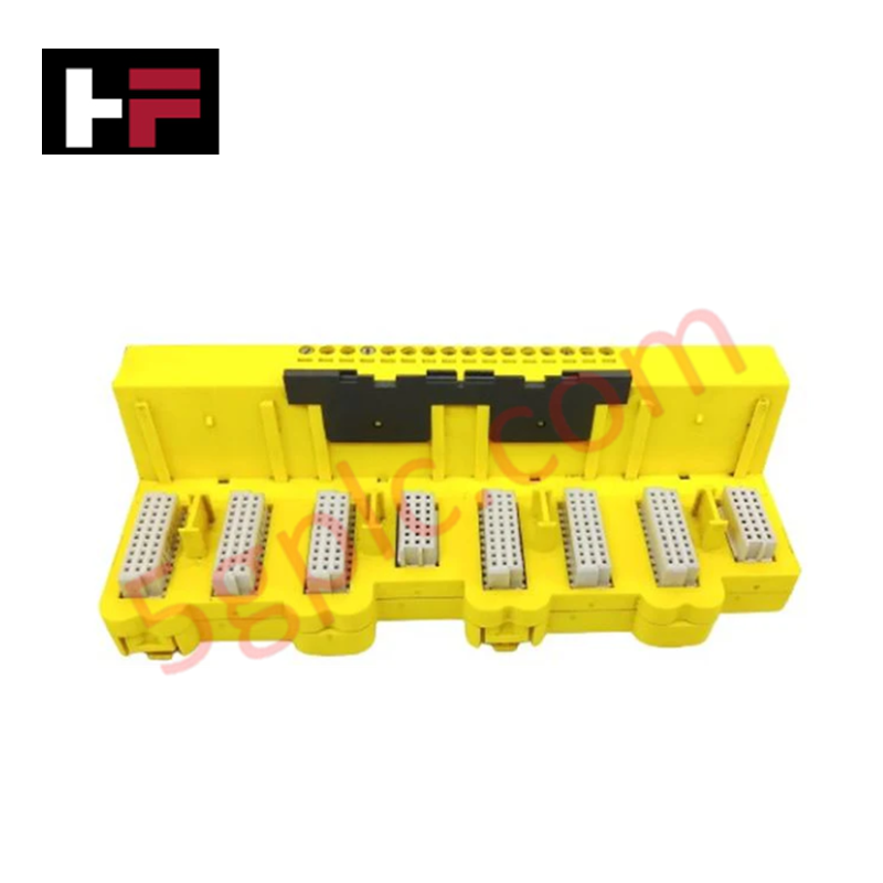
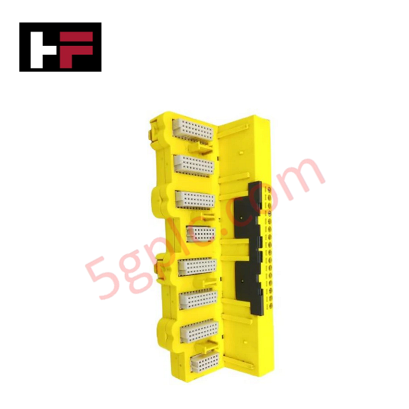
The Emerson KJ2201X1-JA1, also cataloged as the KJ2201X1-JA1 Redundant Terminal Block, operates as a dedicated hardware component for physical signal distribution within DeltaV controller subsystems. This hardware unit provides direct electrical termination pathways, routing dual-channel redundant I/O line configurations directly to localized interface cards across the control backplane assembly.
Hardware Specifications
| Parameter | Specification |
| Model | KJ2201X1-JA1 |
| Brand | Emerson |
| Origin | USA |
| Weight | 0.2 kg |
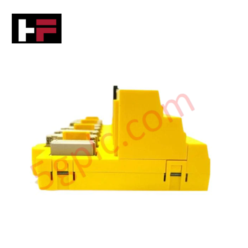
| Dimensions | 4.4 cm x 10.2 cm x 10.8 cm |
| Operating Temp | -40 deg C to +70 deg C |
| Power Consumption | Passive electrical distribution pathway |
| Connection Architecture | Redundant terminal block interface |
| Physical Layer | Multi-position terminal contact screws |
Channel-To-Channel Isolation and DCS Synchronization
Mechanical execution of this redundant termination infrastructure relies on discrete physical trace layouts to safeguard distributed loop parameters. The block incorporates galvanic channel-to-channel isolation parameters that mitigate the risk of cross-channel short circuits or common-mode electrical noise interfering with parallel monitoring lines. This physical segregation enables parallel 4-20 mA HART loop protocol routing and continuous signal synchronization between redundant online interface modules without introducing cross-talk hazards or signal attenuation.
Frequently Asked Questions
Q: How does this passive terminal block respond during a hot-swap operation of an attached interface card?
A: The terminal block remains completely static and secured to the carrier rail. Internal gold-plated contact pins allow secondary interface modules to be inserted or extracted under power without breaking the physical field circuit wiring loops or interrupting the active parallel channel data stream.
Q: Does a short circuit on one terminal path affect the redundant signal track?
A: No. The integrated channel-to-channel isolation path ensures that an electrical fault or localized grounding failure on a specific terminal point is contained, permitting the redundant branch to continue undisturbed communication with the active controller.
Field Installation Guidelines
-
Carrier Rail Attachment: Snap the termination block base directly onto the designated carrier rail structure. Tighten the integrated mechanical locking screws to prevent lateral movement or physical displacement under high-vibration conditions.
-
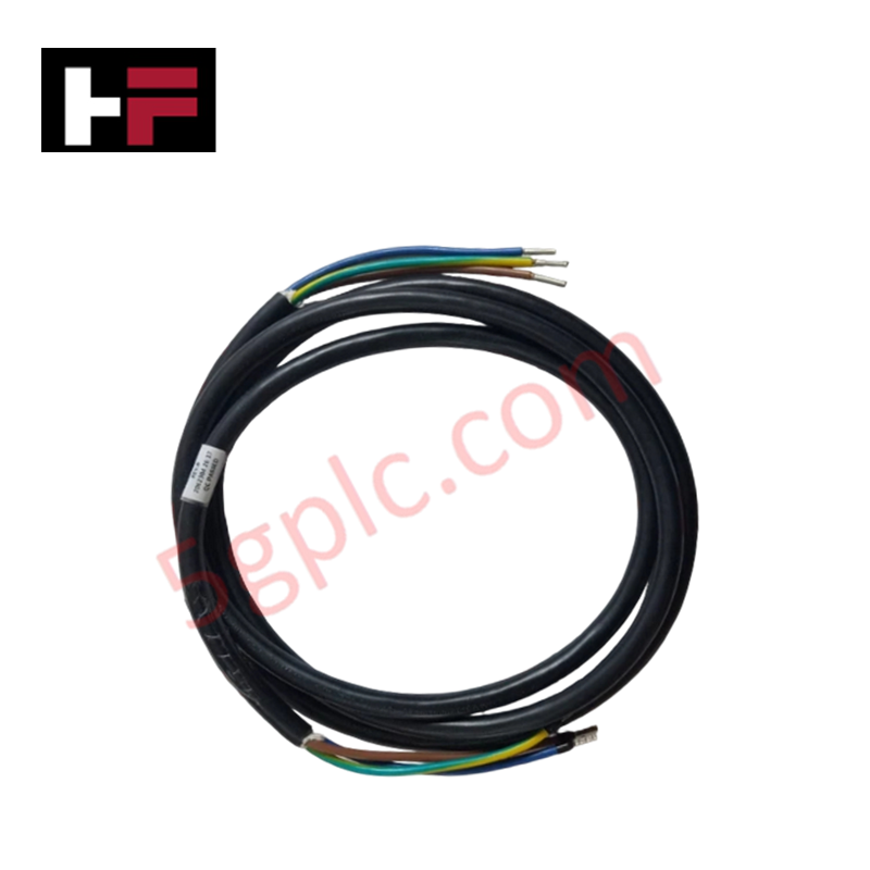
Wiring Terminal Allocation: Strip field conductors back to the factory specification and insert them completely into the clamp terminals. Torque each terminal screw to the certified rating to verify consistent low-resistance electrical contact.
-
Shield Grounding Layout: Terminate all instrument cable shields at the main cabinet ground bar only. Maintain a strict single-point grounding configuration across the termination matrix to prevent low-frequency circulating currents from corrupting the instrumentation loops.
-
Conduit Separation Distance: Maintain a minimum physical distance of 300 mm between low-voltage instrument signals terminating at this block and any high-power motor or distribution lines inside the cabinet tracking lines to suppress inductive noise.
Additional Information
- 100% Genuine Parts: All products are original and authentic, ensuring reliable industrial performance.
- 30-Day Refund Guarantee: Return any in-stock item within 30 days in original, unopened packaging for a full refund (excluding shipping and fees).
- 12-Month Warranty: Covers defects in materials or workmanship; excludes misuse, normal wear, or unauthorized modifications.
- Worldwide Shipping: We ship via USPS, UPS, FedEx, and DHL. Delivery times vary by country and may be subject to customs or import fees.
- Support & Contact: Technical and warranty assistance is available anytime. Contact us here: Contact.
- Purchase Guidance: Check product specifications and compatibility carefully before ordering to ensure proper application.


Tech & Buying Guide

Essential Motion Control Commands: A Practical Guide for Engineers
Automation engineers often rely on precise position and speed control to drive modern factory machinery. Modern industrial systems, such as Programmable Logic Controllers (PLCs) and Distributed Control Systems (DCS), depend heavily on standardized motion instructions. Mastering these commands ensures operational safety, protects mechanical components, and optimizes cycle times across production lines.

The Role of Intrinsic Safety Barriers in PLC and DCS Architectures
Implementing robust protection in hazardous industrial environments represents a fundamental safety requirement in factory automation. Process facilities often handle volatile gases, dusts, and chemical agents that pose significant combustion risks. Consequently, control system engineers must deploy energy-limiting interfaces to isolate safe-area control cabinets from hazardous-area field instrumentation. This article examines the function, selection, and electrical principles of intrinsic safety barriers within modern PLC and DCS networks.

Architectural Selection and Scale Classification of PLC Systems in Industrial Automation
Selecting the correct control platform represents a foundational engineering decision in factory automation. System designers must carefully balance technical parameters against long-term operational requirements when implementing a Programmable Logic Controller (PLC). This article examines the critical evaluation metrics, physical scale classifications, and operational architectures of modern control systems.