


Product Details
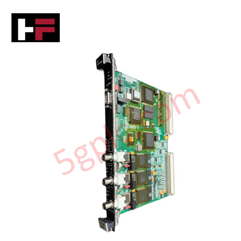
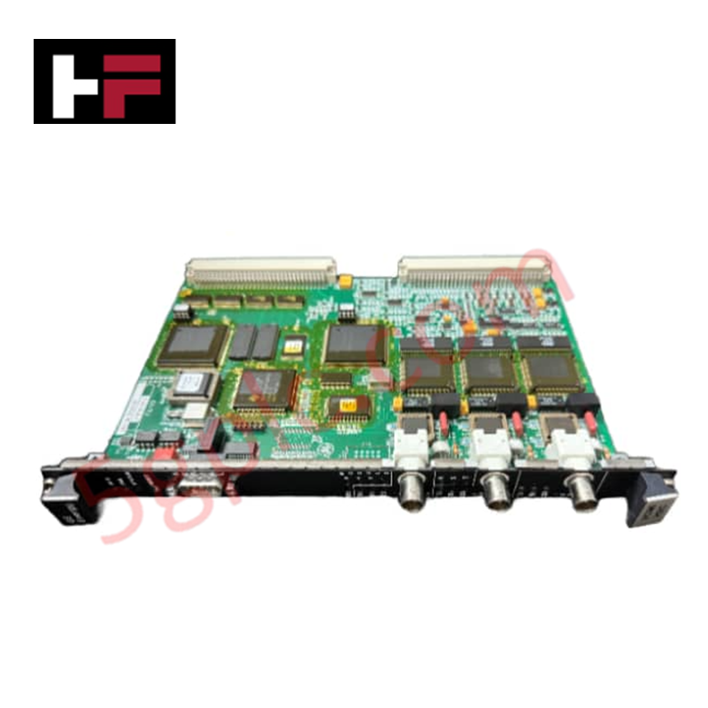
Configured for data exchange and system coordination in Mark VI control environments, the GE IS215VCMIH2CB (IS215VCMIH2CB VME Communications Card) provides direct physical/electrical execution. This VME bus master manages data transfer between controllers, I/O boards, and the IONet control network, while maintaining power supply monitoring and diagnostic functions for rack-mounted components.
Hardware Specifications
| Parameter | Specification |
|---|---|
| Model | IS215VCMIH2CB |
| Brand | General Electric |
| Origin | USA |
| Weight | Not specified |
| Dimensions | Standard VME card form factor |
| Operating Temp | Industrial standard range |
| Power Consumption | Monitors 5 V, 12 V, 15 V, 28 V rails |
| Number of Channels | 8 |
| Span | 0.3532 to 4.054 V |
Industrial Control and Drives Technical Characteristics
The IS215VCMIH2CB functions as the VME bus master, governing data flow within the control and I/O racks. It assigns unique identification for all boards and associated terminal boards to ensure correct network addressing. The module provides continuous tracking of multiple internal power supply buses; alarms are triggered when voltage deviations exceed thresholds of 3.5 percent for 5 V, 12 V, and 15 V supplies, or 5.5 percent for 28 V supplies. Optimal operation depends on backplane bus communication velocity and firmware flash compatibility to ensure synchronized data throughput across the IONet infrastructure.
Frequently Asked Questions
Q: Does the IS215VCMIH2CB support hot-swapping within the VME rack?
A: No. The card performs bus master functions and controls data addressing. Removing or inserting this module while the VME rack is energized will result in loss of communication and potential damage to the VME bus backplane.
Q: How does the module handle voltage monitoring alarms?
A: The module tracks voltage levels on the 5 V, 12 V, 15 V, and 28 V buses. When these levels exceed configured alarm thresholds, the card generates diagnostic signals, enabling the Mark VI controller to identify power supply degradation before a trip condition occurs.
Field Installation Guidelines
- VME Bus Insertion: Ensure the VME rack is de-energized. Align the card with the rack guides and slide it into the designated VME slot, ensuring the backplane pins are seated fully and the locking ejector handles are secure.
- Network Connectivity: Connect the IONet cables to the designated ports. Use shielded communication cables to minimize electromagnetic interference, which can disrupt deterministic data exchange.
- Grounding: Ensure the VME rack assembly is bonded to the system common earth ground. This provides a necessary reference for the card's power monitoring circuits and helps mitigate common-mode noise.
- Configuration Verification: Following installation, verify that the module is correctly identified in the rack configuration software. Ensure that the addressing and ID assignment processes match the physical layout of the I/O and terminal boards to prevent bus conflicts.
Additional Information
- 100% Genuine Parts: All products are original and authentic, ensuring reliable industrial performance.
- 30-Day Refund Guarantee: Return any in-stock item within 30 days in original, unopened packaging for a full refund (excluding shipping and fees).
- 12-Month Warranty: Covers defects in materials or workmanship; excludes misuse, normal wear, or unauthorized modifications.
- Worldwide Shipping: We ship via USPS, UPS, FedEx, and DHL. Delivery times vary by country and may be subject to customs or import fees.
- Support & Contact: Technical and warranty assistance is available anytime. Contact us here: Contact.
- Purchase Guidance: Check product specifications and compatibility carefully before ordering to ensure proper application.


Tech & Buying Guide

Essential Motion Control Commands: A Practical Guide for Engineers
Automation engineers often rely on precise position and speed control to drive modern factory machinery. Modern industrial systems, such as Programmable Logic Controllers (PLCs) and Distributed Control Systems (DCS), depend heavily on standardized motion instructions. Mastering these commands ensures operational safety, protects mechanical components, and optimizes cycle times across production lines.

The Role of Intrinsic Safety Barriers in PLC and DCS Architectures
Implementing robust protection in hazardous industrial environments represents a fundamental safety requirement in factory automation. Process facilities often handle volatile gases, dusts, and chemical agents that pose significant combustion risks. Consequently, control system engineers must deploy energy-limiting interfaces to isolate safe-area control cabinets from hazardous-area field instrumentation. This article examines the function, selection, and electrical principles of intrinsic safety barriers within modern PLC and DCS networks.

Architectural Selection and Scale Classification of PLC Systems in Industrial Automation
Selecting the correct control platform represents a foundational engineering decision in factory automation. System designers must carefully balance technical parameters against long-term operational requirements when implementing a Programmable Logic Controller (PLC). This article examines the critical evaluation metrics, physical scale classifications, and operational architectures of modern control systems.