


Product Details
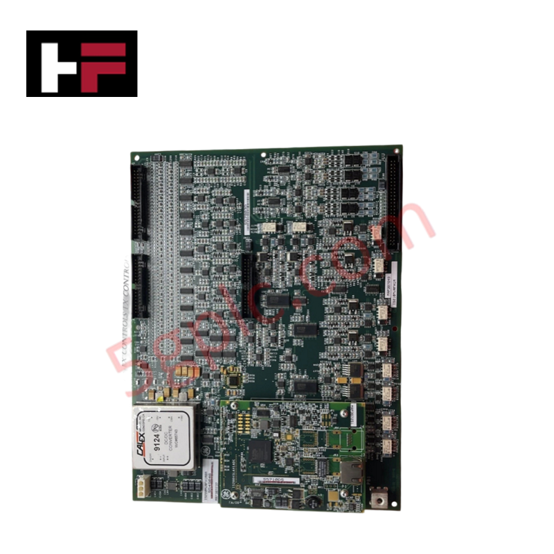
Configured for signal interfacing in Mark VIe control systems, the GE IS210MVRFH1A (IS210MVRFH1A Interface Board) provides direct physical execution of computational and signal routing tasks. This hardware component serves as the primary 6U high VME interface board utilized to execute signal management and data processing across Mark VIe platforms.
Hardware Specifications
| Parameter | Specification |
|---|---|
| Model | IS210MVRFH1A |
| Brand | GE |
| Origin | USA |
| Weight | Not specified |
| Dimensions | 6U VME form factor; 0.787 inch wide |
| Operating Temp | -30 deg C to 65 deg C |
| Power Consumption | System-dependent |
| Core Performance | TMS320C32 processor |
Industrial Control and Firmware Compatibility
The IS210MVRFH1A incorporates a TMS320C32 digital signal processor to facilitate high-speed data handling and control logic execution. As a 6U VME-based module, it requires strict adherence to VME backplane bus communication velocity specifications to maintain synchronization with other system processors. Firmware flash compatibility between the interface board and the host Mark VIe controller is mandatory to ensure accurate data packet processing. The board is architected to support I/O density scaling by providing localized signal processing capabilities, which minimizes the communication load on the primary control network and improves real-time response for field-connected equipment. Users should ensure all backplane slots are keyed correctly for the VME interface to prevent bus contention and hardware damage during system initialization.
Frequently Asked Questions
Q: Does the IS210MVRFH1A support hot-swapping within the VME chassis?
A: No. The VME interface architecture does not support live insertion or removal. The chassis backplane must be de-energized before extracting or installing the interface board to prevent damage to the TMS320C32 processor or backplane pins.
Q: Is this board firmware-specific to the host controller?
A: Yes. The IS210MVRFH1A requires specific firmware revision sets that must match the host controller’s ControlST software version to ensure deterministic data transfer and operational integrity.
Field Installation Guidelines
- Mounting: Insert the 6U VME module into the designated slot, ensuring firm engagement with the backplane connectors. Utilize the integrated locking levers to secure the board and ensure proper mechanical grounding to the chassis.
- ESD Protection: Use a wrist strap connected to a common ground point when handling the board to prevent electrostatic discharge damage to the surface-mount components.
- Cable Management: Route interface cables away from high-voltage power lines and motor drives to prevent induced electromagnetic interference on signal lines.
- Verification: Perform a power-on self-test (POST) via the control software to verify that the board is correctly identified and communicating over the backplane bus before initiating active control operations.
Additional Information
- 100% Genuine Parts: All products are original and authentic, ensuring reliable industrial performance.
- 30-Day Refund Guarantee: Return any in-stock item within 30 days in original, unopened packaging for a full refund (excluding shipping and fees).
- 12-Month Warranty: Covers defects in materials or workmanship; excludes misuse, normal wear, or unauthorized modifications.
- Worldwide Shipping: We ship via USPS, UPS, FedEx, and DHL. Delivery times vary by country and may be subject to customs or import fees.
- Support & Contact: Technical and warranty assistance is available anytime. Contact us here: Contact.
- Purchase Guidance: Check product specifications and compatibility carefully before ordering to ensure proper application.


Tech & Buying Guide

Understanding Dry Contacts in PLC Wiring: An Industrial Automation Guide
Mastering contact switching principles is essential for reliable control panels. Field devices and PLCs interface through dry or wet contacts. This technical guide examines the mechanics of dry contacts, explores their wiring architectures, and evaluates their key advantages in industrial automation.

Ultimate Commissioning Checklist for Industrial Automation Systems: An Engineering Guide
Commissioning is the most decisive phase of an industrial automation project, transforming control hardware and software into an operational facility. Thorough testing prevents costly startup delays and builds customer confidence. This guide covers essential checklists, electrical standards, and best practices.

Redundant Automation Systems: Core Architecture, Business Value, and Technical Advantages
Unplanned downtime poses a major financial threat to process manufacturing. To prevent costly interruptions, engineers deploy redundant PLC and DCS architectures that ensure continuous operation when hardware fails. This technical guide explores redundancy principles, critical system nodes, and real-world scenarios.