


Product Details
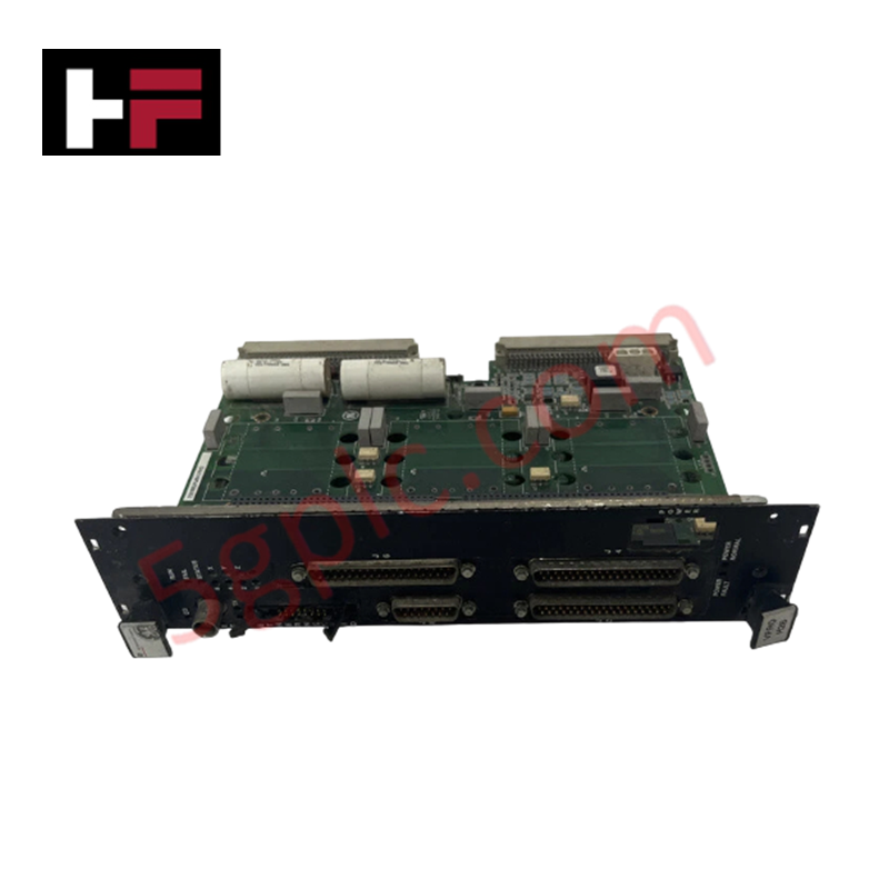
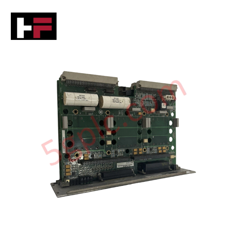
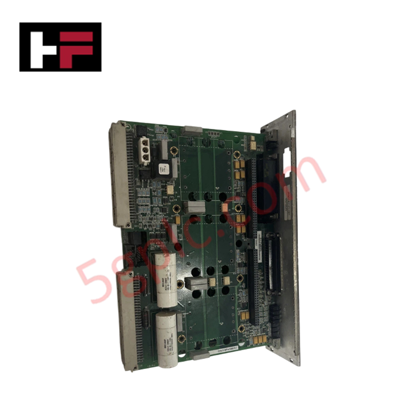
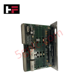
The General Electric IS200VPROH2B, also cataloged as the IS200VPROH2B Turbine Protection Board, operates as a dedicated hardware component for emergency overspeed protection within Mark VI control system platforms. This module provides direct physical execution of independent turbine monitoring, functioning in tandem with TPRO and TREG terminal boards to initiate safety mechanisms during critical operation.
Hardware Specifications
| Parameter | Specification |
|---|---|
| Model | IS200VPROH2B |
| Brand | General Electric |
| Origin | USA |
| Dimensions | Standard PCB form factor |
| Operating Temp | 0 deg C to 60 deg C |
| Power Consumption | Rack dependent |
| MPU Pulse Rate | 2 Hz to 20 kHz |
| Frame Rate | Up to 100 Hz |
| Input Filter | Hardware filter, 4 ms |
Firmware Flash Compatibility and Deterministic Performance
The IS200VPROH2B board manages turbine speed inputs through a dedicated MPU pulse rate range of 2 Hz to 20 kHz, ensuring deterministic overspeed detection. The module architecture incorporates a hardware-level 4 ms input filter to suppress signal noise, ensuring that protection triggers are based on verified rotational data. When performing maintenance or system upgrades, firmware flash compatibility must be validated against the existing Mark VI control rack version to prevent synchronization errors between the VPRO system and the primary turbine controller. The board utilizes high-velocity backplane bus communication to ensure that protection signals are propagated with minimal latency, maintaining independent emergency functionality regardless of the status of the main turbine control software.
Frequently Asked Questions
Q: Does the IS200VPROH2B board support hot-swapping in an active Mark VI rack?
A: No. Standard procedure requires the removal of input power and total de-energization of the VPRO system rack before any module is extracted or inserted to protect backplane pins and onboard logic.
Q: How is the 4 ms hardware filter utilized during overspeed detection?
A: The 4 ms hardware filter is applied to the incoming MPU pulse signals to prevent nuisance tripping caused by high-frequency electromagnetic interference or transient signal fluctuations on the MPU cabling.
Field Installation Guidelines
- Mounting: Seat the board firmly within the designated VPRO system slot, ensuring the backplane connectors align perfectly before engaging the locking tabs.
- Grounding: Ensure the rack assembly is bonded to the system common earth. The VPRO module relies on a stable ground reference to maintain the accuracy of the frequency-to-digital conversion circuits.
- Wiring: Route MPU pulse input cabling through shielded, twisted-pair conduit. Keep these lines separated from power supply and actuator control wiring to prevent crosstalk and signal distortion.
- Inspection: Verify that the board is correctly keyed for the VPRO slot. Do not force the board if resistance is encountered; inspect the backplane for debris or bent pins before re-attempting insertion.
Additional Information
- 100% Genuine Parts: All products are original and authentic, ensuring reliable industrial performance.
- 30-Day Refund Guarantee: Return any in-stock item within 30 days in original, unopened packaging for a full refund (excluding shipping and fees).
- 12-Month Warranty: Covers defects in materials or workmanship; excludes misuse, normal wear, or unauthorized modifications.
- Worldwide Shipping: We ship via USPS, UPS, FedEx, and DHL. Delivery times vary by country and may be subject to customs or import fees.
- Support & Contact: Technical and warranty assistance is available anytime. Contact us here: Contact.
- Purchase Guidance: Check product specifications and compatibility carefully before ordering to ensure proper application.


Tech & Buying Guide

Redundant Automation Systems: Ensuring Continuous Uptime in Critical Control Infrastructure
System reliability directly determines operational profitability across high stakes process industries. Modern industrial automation platforms must eliminate single points of failure to prevent catastrophic shutdowns. Deploying fault tolerant architecture safeguards complex facilities against unexpected hardware glitches, network disruptions, and maintenance outages.

Understanding Types of Noise in Electronic Circuits and Control Systems
Signal integrity directly determines measurement accuracy and loop stability across industrial automation environments. Electronic noise introduces unwanted stochastic interference into analog loops, sensor feedback lines, and digital fieldbus networks. Understanding how intrinsic electronic noise and external electromagnetic interference manifest allows control engineers to optimize signal conditioning and shield sensitive instrumentation effectively.

Why 24V DC Power Supplies Standardize Modern Industrial Automation
Industrial control cabinets worldwide rely on 24V DC as the universal power standard for field instrumentation, sensors, and controllers. Walk into any manufacturing plant, and you will find PLCs, human-machine interfaces (HMIs), and smart actuators running on extra-low voltage DC. Standardizing on 24V DC enhances operational safety, lowers cabinet footprint, and maintains steady control performance across factory networks.