


Product Details
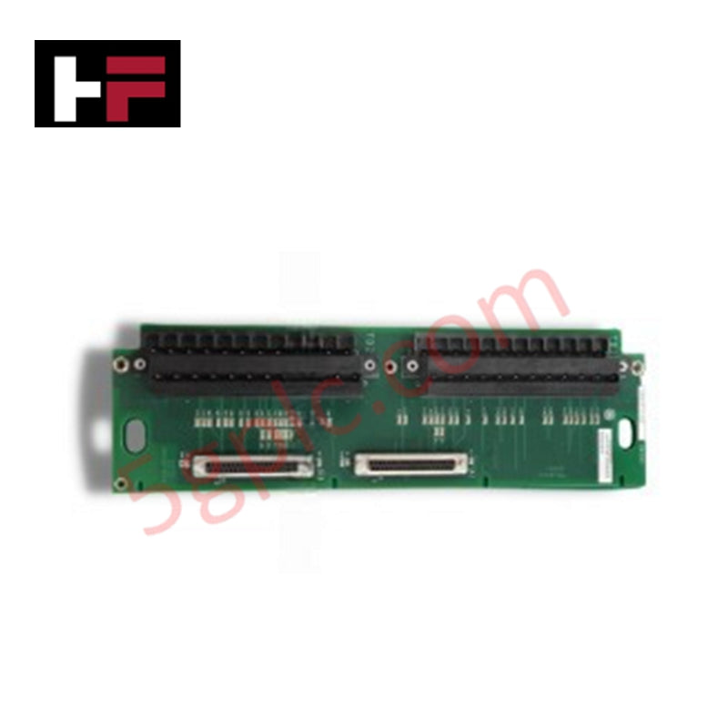
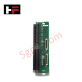
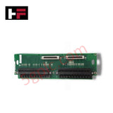
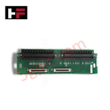
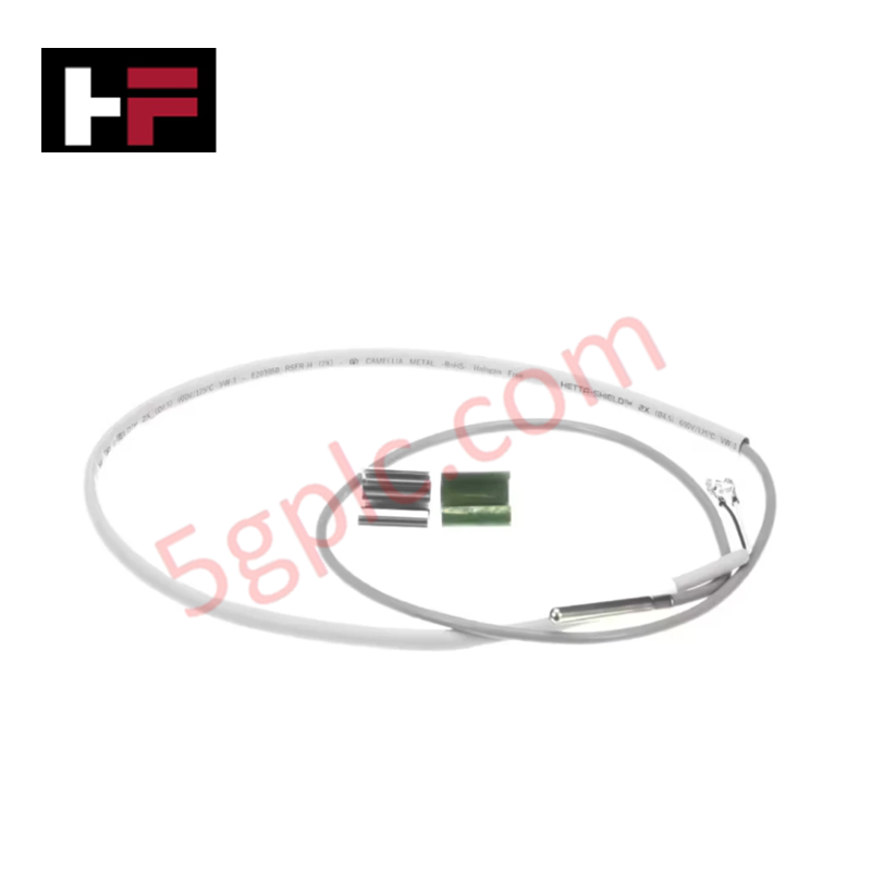
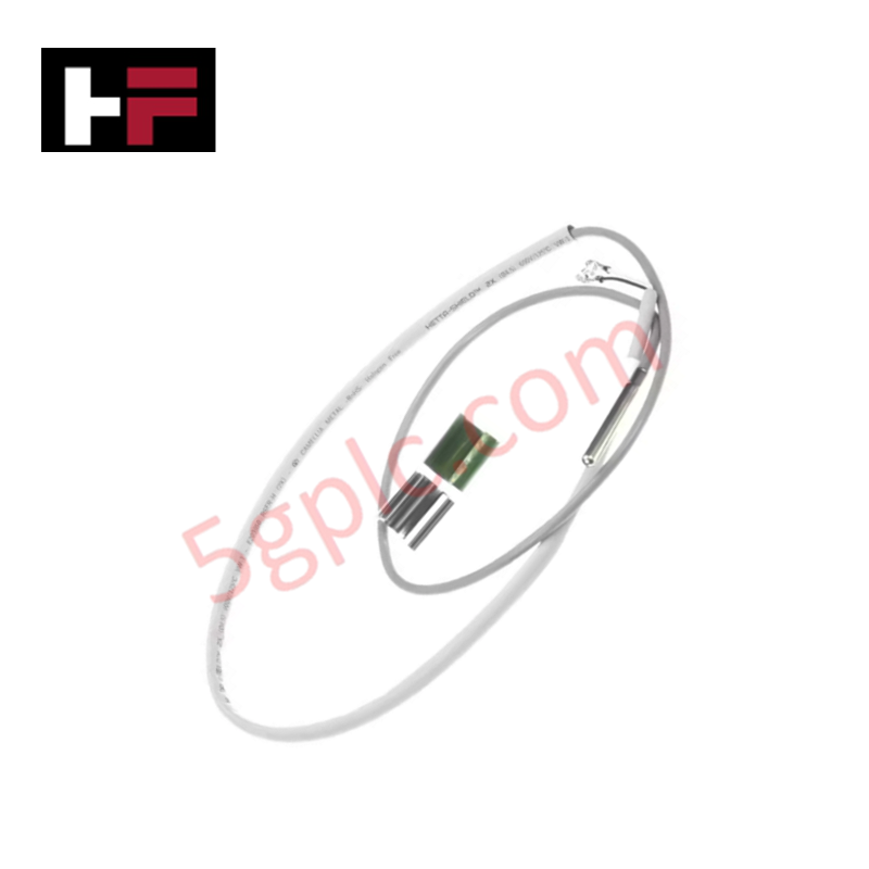
Configured for discrete temperature sensing in Mark VIe control systems, the GE IS200TRTDH1D (IS200TRTDH1D RTD Input Terminal Board) provides direct physical/electrical execution. This terminal board accepts 16 three-wire RTD inputs via two barrier-type terminal blocks, providing integrated surge and high-frequency noise suppression to maintain signal integrity before data is processed by the associated PRTD I/O packs.
Hardware Specifications
| Parameter | Specification |
|---|---|
| Model | IS200TRTDH1D |
| Brand | General Electric |
| Origin | USA |
| Weight | Not specified |
| Dimensions | Standard Mark VIe terminal board form factor |
| Operating Temp | Industrial standard range |
| Power Consumption | Dependent on input loop configuration |
| Inputs | 16 x 3-wire RTD |
Industrial Control and Drives Technical Characteristics
The TRTDH1D module architecture facilitates simplex operation, interfacing with two PRTD I/O packs to capture 16 RTD signals. The design incorporates dedicated noise suppression circuitry to mitigate EMI at the input stage, ensuring high-fidelity temperature data conversion. Deterministic communication is managed through I/O processor integration; users must ensure firmware flash compatibility between the PRTD packs and the central control processor to maintain accurate temperature reporting. I/O density is scaled through the use of high-density terminal blocks, supporting up to #12 AWG wire gauge, requiring precise adherence to backplane bus communication velocity settings for synchronized data scanning.
Frequently Asked Questions
Q: Does the IS200TRTDH1D support triple modular redundancy (TMR)?
A: No. The TRTDH1D is designated for simplex application topologies. It interfaces with two PRTD I/O packs to provide 16 inputs, whereas TMR configurations require different terminal board hardware variants (e.g., TRTDH1B) capable of fanning inputs to three VRTD boards.
Q: How should double-shielded RTD wiring be terminated on this board?
A: All double-shielded wires must be terminated at the shield terminal strip integrated into the terminal blocks. These strips are connected to the chassis ground, providing a continuous path to drain electromagnetic interference away from the RTD sensing elements.
Field Installation Guidelines
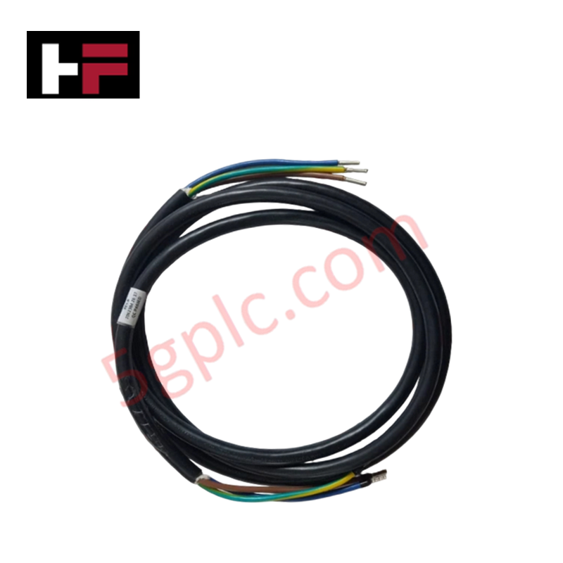
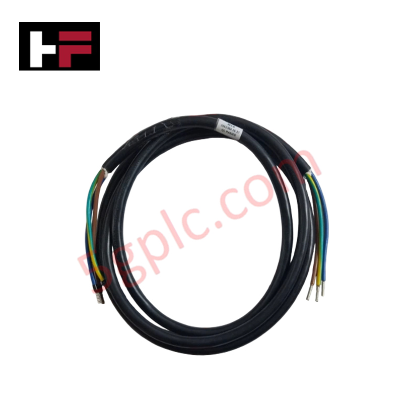
- Wiring Termination: Land RTD signal wires directly on the barrier-type terminal blocks. Each of the 24-terminal blocks accepts up to #12 AWG wire. Secure terminal blocks using the two provided mounting screws to prevent vibration-induced loosening.
- Shielding: Utilize double-shielded wire for all RTD connections. Terminate shields at the board's shield terminal strip; ensure end shields are correctly terminated at the field device to eliminate ground loops.
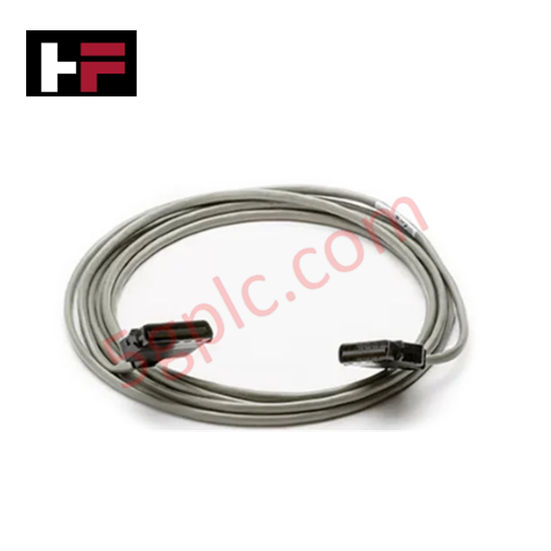
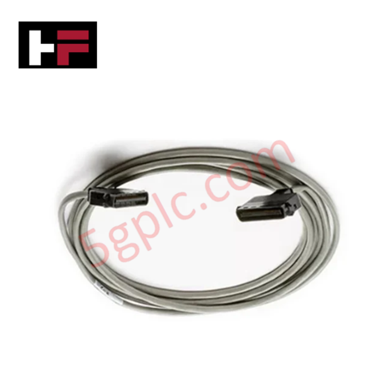
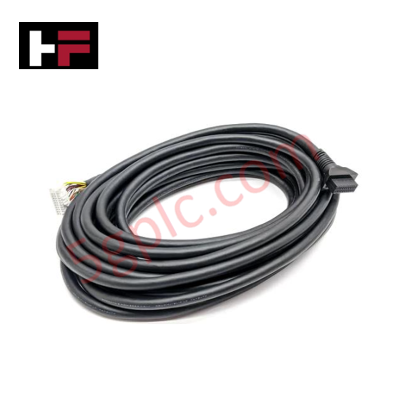
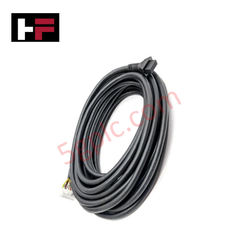
- Processor Interfacing: Connect the board to the two PRTD I/O packs using the dedicated DC-type connectors. Verify that these connections are fully seated and free of debris to maintain reliable signal transmission to the I/O processors.
- Noise Mitigation: Ensure the terminal board chassis is bonded to a low-impedance earth ground. Avoid running RTD input cables in parallel with high-voltage AC power lines to prevent signal induction and measurement errors.
Additional Information
- 100% Genuine Parts: All products are original and authentic, ensuring reliable industrial performance.
- 30-Day Refund Guarantee: Return any in-stock item within 30 days in original, unopened packaging for a full refund (excluding shipping and fees).
- 12-Month Warranty: Covers defects in materials or workmanship; excludes misuse, normal wear, or unauthorized modifications.
- Worldwide Shipping: We ship via USPS, UPS, FedEx, and DHL. Delivery times vary by country and may be subject to customs or import fees.
- Support & Contact: Technical and warranty assistance is available anytime. Contact us here: Contact.
- Purchase Guidance: Check product specifications and compatibility carefully before ordering to ensure proper application.


Tech & Buying Guide

Essential Motion Control Commands: A Practical Guide for Engineers
Automation engineers often rely on precise position and speed control to drive modern factory machinery. Modern industrial systems, such as Programmable Logic Controllers (PLCs) and Distributed Control Systems (DCS), depend heavily on standardized motion instructions. Mastering these commands ensures operational safety, protects mechanical components, and optimizes cycle times across production lines.

The Role of Intrinsic Safety Barriers in PLC and DCS Architectures
Implementing robust protection in hazardous industrial environments represents a fundamental safety requirement in factory automation. Process facilities often handle volatile gases, dusts, and chemical agents that pose significant combustion risks. Consequently, control system engineers must deploy energy-limiting interfaces to isolate safe-area control cabinets from hazardous-area field instrumentation. This article examines the function, selection, and electrical principles of intrinsic safety barriers within modern PLC and DCS networks.

Architectural Selection and Scale Classification of PLC Systems in Industrial Automation
Selecting the correct control platform represents a foundational engineering decision in factory automation. System designers must carefully balance technical parameters against long-term operational requirements when implementing a Programmable Logic Controller (PLC). This article examines the critical evaluation metrics, physical scale classifications, and operational architectures of modern control systems.