


Product Details
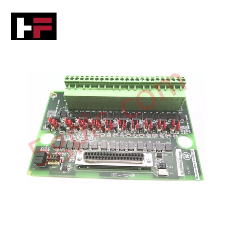
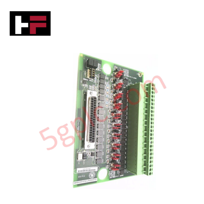
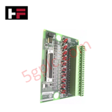
Configured for signal termination in Mark VIe control architectures, the GE IS200STAIH2A (IS200STAIH2A Simplex Analog Input Terminal Board) provides direct physical and electrical execution of multi-channel sensor data routing and 24 VDC loop excitation.
Hardware Specifications
| Parameter | Specification |
|---|---|
| Model | IS200STAIH2A |
| Brand | General Electric |
| Origin | USA |
| Weight | Standard terminal board assembly |
| Dimensions | 15.9 cm x 10.2 cm |
| Operating Temp | -30 deg C to +65 deg C |
| Power Consumption | 24 VDC (Excitation) |
| Analog Channels | 12 |
| Lead Resistance | 15 Ohm (Maximum) |
Profinet / EtherNet/IP Deterministic Networks
The IS200STAIH2A serves as an interface node within the Mark VIe ecosystem, facilitating standardized signal conditioning between field-mounted instrumentation and system I/O packs. The board architecture supports deterministic backplane bus communication velocity, ensuring that analog data acquisition remains synchronized with controller scan cycles. Firmware flash compatibility is managed via the host I/O pack configuration, which defines the scaling and filtering parameters for the 12 input channels. The module supports I/O density scaling through its compact terminal layout, allowing for high-integrity signal transmission while minimizing signal degradation over field cabling. The surface-mount technology utilized in the PCB construction maintains consistent electrical impedance, supporting precision signal distribution across the simplex architecture.
Frequently Asked Questions
Q: Does the IS200STAIH2A support hot-swapping under load?
A: No. Replacement of the terminal board requires the associated I/O loop to be de-energized to prevent transient currents from damaging the analog input circuitry or the connected field devices.
Q: Is the 24 VDC excitation voltage configurable on a per-channel basis?
A: No. The 24 VDC excitation is common across the designated input channels on the board. Ensure all field instruments connected to these inputs are compatible with the shared excitation voltage.
Field Installation Guidelines
- Mounting: Secure the board within the cabinet using the provided mounting holes. Maintain adequate clearance from high-voltage AC lines to prevent induced noise on the analog signal paths.
- Wiring: Terminate field wiring using the designated terminal blocks. Maintain consistent polarity for all analog loops and ensure that cable shields are grounded at a single, low-impedance point to minimize common-mode noise.
- Loop Resistance: Ensure that the total lead resistance of the field cabling does not exceed 15 Ohm to maintain the accuracy of the signal transmission.
- Environment: Verify that the cabinet internal temperature remains within the specified range of -30 deg C to +65 deg C. Provide sufficient airflow to prevent heat accumulation around the board's passive and active components.
- Verification: Prior to energization, conduct a point-to-point electrical check to verify wiring integrity and polarity. Use the Mark VIe diagnostic tool to confirm that all 12 analog inputs are correctly registered by the system.
Additional Information
- 100% Genuine Parts: All products are original and authentic, ensuring reliable industrial performance.
- 30-Day Refund Guarantee: Return any in-stock item within 30 days in original, unopened packaging for a full refund (excluding shipping and fees).
- 12-Month Warranty: Covers defects in materials or workmanship; excludes misuse, normal wear, or unauthorized modifications.
- Worldwide Shipping: We ship via USPS, UPS, FedEx, and DHL. Delivery times vary by country and may be subject to customs or import fees.
- Support & Contact: Technical and warranty assistance is available anytime. Contact us here: Contact.
- Purchase Guidance: Check product specifications and compatibility carefully before ordering to ensure proper application.


Tech & Buying Guide

Essential Motion Control Commands: A Practical Guide for Engineers
Automation engineers often rely on precise position and speed control to drive modern factory machinery. Modern industrial systems, such as Programmable Logic Controllers (PLCs) and Distributed Control Systems (DCS), depend heavily on standardized motion instructions. Mastering these commands ensures operational safety, protects mechanical components, and optimizes cycle times across production lines.

The Role of Intrinsic Safety Barriers in PLC and DCS Architectures
Implementing robust protection in hazardous industrial environments represents a fundamental safety requirement in factory automation. Process facilities often handle volatile gases, dusts, and chemical agents that pose significant combustion risks. Consequently, control system engineers must deploy energy-limiting interfaces to isolate safe-area control cabinets from hazardous-area field instrumentation. This article examines the function, selection, and electrical principles of intrinsic safety barriers within modern PLC and DCS networks.

Architectural Selection and Scale Classification of PLC Systems in Industrial Automation
Selecting the correct control platform represents a foundational engineering decision in factory automation. System designers must carefully balance technical parameters against long-term operational requirements when implementing a Programmable Logic Controller (PLC). This article examines the critical evaluation metrics, physical scale classifications, and operational architectures of modern control systems.