


Product Details
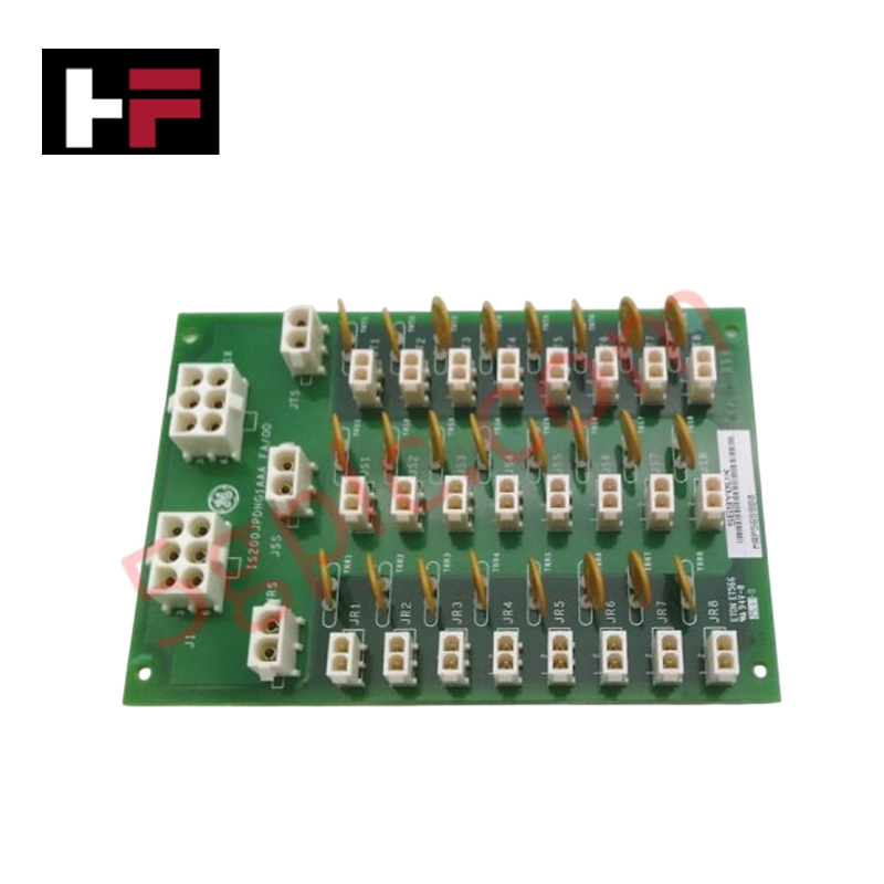
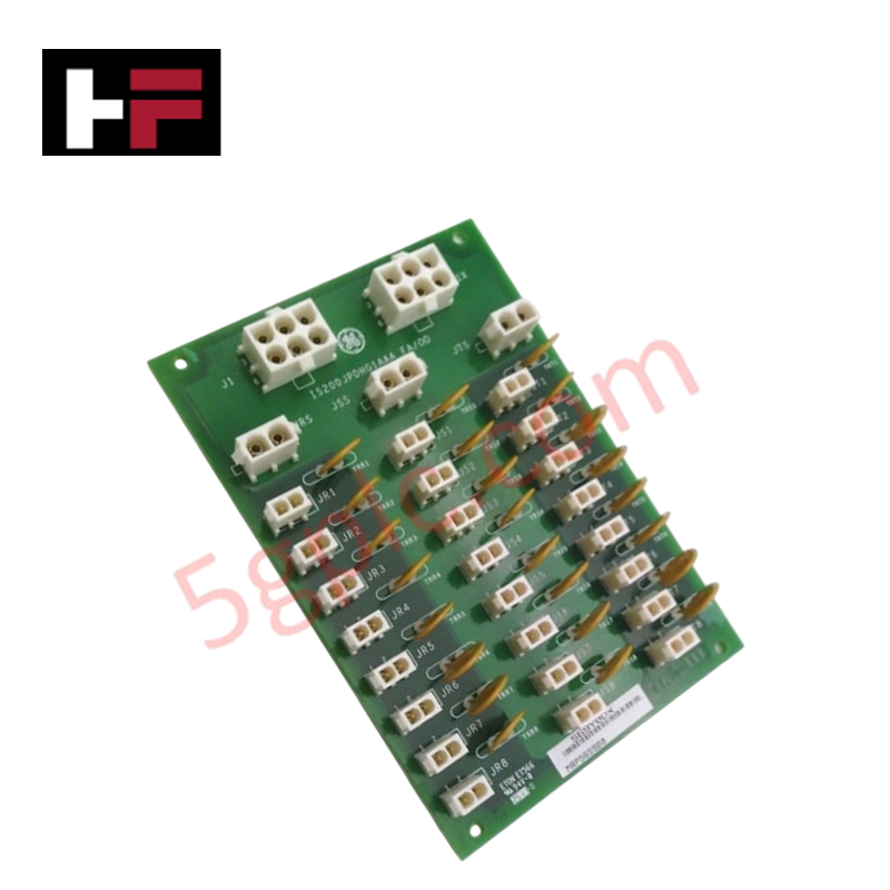
Configured for power distribution in Mark VI Speedtronic turbine control systems, the General Electric IS200JPDHG1A (IS200JPDHG1A Power Distribution Card) provides direct electrical execution of protected control power delivery to I/O packs. This hardware component serves as the primary distribution interface utilized to execute power load management and transient surge suppression across turbine control platform architectures.
Hardware Specifications
| Parameter | Specification |
|---|---|
| Model | IS200JPDHG1A |
| Brand | General Electric |
| Dimensions | Standard PCB form factor |
| Operating Temp | Standard industrial ambient range |
| Power Consumption | 125 V dc input |
| Core Performance | 24 varistors; 24 output distribution channels |
Backplane Bus Communication and Deterministic Networks
The IS200JPDHG1A functions within the Mark VI control architecture to distribute regulated power to peripheral I/O packs. The board utilizes an array of twenty-four varistors arranged in three rows to provide transient voltage suppression, ensuring that power distribution remains stable despite upstream fluctuations. Deterministic power delivery is maintained through a daisy-chain capability via the J1 and J1X connectors. When configuring multiple boards in a series, total input current must be constrained to the thermal rating of the primary J1 input plug to avoid degradation of the distribution integrity. Firmware flash compatibility and system power monitoring are managed at the cabinet level; however, the board ensures I/O density scaling by providing dedicated, protected output channels to individual I/O packs.
Frequently Asked Questions
Q: Are the output distribution channels hot-swappable?
A: No. The board serves as a passive power distribution component. All input power (125 V dc) must be isolated at the source before adding or removing connections to the JR1-JR8, JS1-JS8, or JT1-JT8 output plugs to prevent arcing.
Q: What are the restrictions when daisy-chaining multiple IS200JPDHG1A boards?
A: When daisy-chaining via J1 and J1X, the cumulative current draw of all downstream loads must not exceed the maximum current capacity of the first board's J1 input connector. Exceeding this limit will cause thermal failure of the input plug.
Field Installation Guidelines
- Mounting: Secure the PCB using standard standoff hardware. Ensure adequate clearance is maintained around the varistor arrays to prevent heat accumulation during operation.
- Wiring: Ensure all wiring complies with Class 1 Division 2, Class 1 Zone 2, and ATEX hazardous location requirements where applicable. Use appropriately rated wire gauge for the 125 V dc supply and ensure all crimp connections on the 2-position and 6-position plugs are mechanically secure.
- Grounding: Terminate the board to a common system ground. In hazardous location installations, follow the specific grounding requirements dictated by UL/ATEX documentation to ensure the intrinsic safety of the distribution path.
- Inspection: Periodically verify the integrity of the twenty-four varistors. Replace the module if any varistor shows physical signs of discoloration or cracking, indicating a prior transient surge event that may have exceeded the component rating.
Additional Information
- 100% Genuine Parts: All products are original and authentic, ensuring reliable industrial performance.
- 30-Day Refund Guarantee: Return any in-stock item within 30 days in original, unopened packaging for a full refund (excluding shipping and fees).
- 12-Month Warranty: Covers defects in materials or workmanship; excludes misuse, normal wear, or unauthorized modifications.
- Worldwide Shipping: We ship via USPS, UPS, FedEx, and DHL. Delivery times vary by country and may be subject to customs or import fees.
- Support & Contact: Technical and warranty assistance is available anytime. Contact us here: Contact.
- Purchase Guidance: Check product specifications and compatibility carefully before ordering to ensure proper application.


Tech & Buying Guide

Redundant Automation Systems: Ensuring Continuous Uptime in Critical Control Infrastructure
System reliability directly determines operational profitability across high stakes process industries. Modern industrial automation platforms must eliminate single points of failure to prevent catastrophic shutdowns. Deploying fault tolerant architecture safeguards complex facilities against unexpected hardware glitches, network disruptions, and maintenance outages.

Understanding Types of Noise in Electronic Circuits and Control Systems
Signal integrity directly determines measurement accuracy and loop stability across industrial automation environments. Electronic noise introduces unwanted stochastic interference into analog loops, sensor feedback lines, and digital fieldbus networks. Understanding how intrinsic electronic noise and external electromagnetic interference manifest allows control engineers to optimize signal conditioning and shield sensitive instrumentation effectively.

Why 24V DC Power Supplies Standardize Modern Industrial Automation
Industrial control cabinets worldwide rely on 24V DC as the universal power standard for field instrumentation, sensors, and controllers. Walk into any manufacturing plant, and you will find PLCs, human-machine interfaces (HMIs), and smart actuators running on extra-low voltage DC. Standardizing on 24V DC enhances operational safety, lowers cabinet footprint, and maintains steady control performance across factory networks.