


Product Details
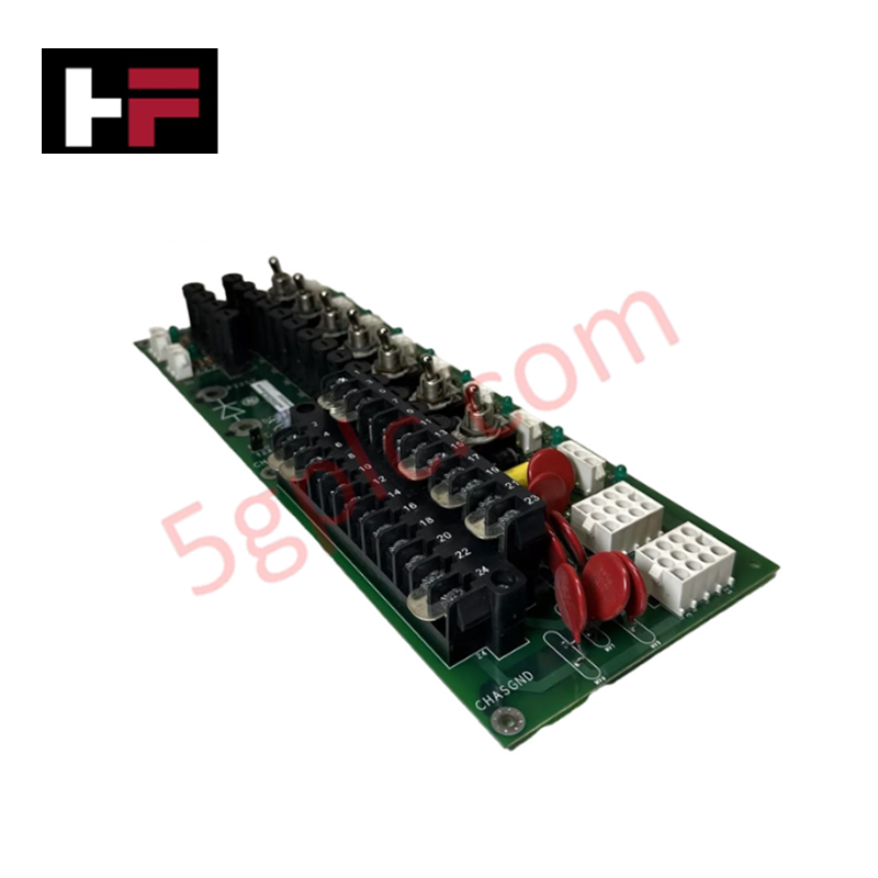
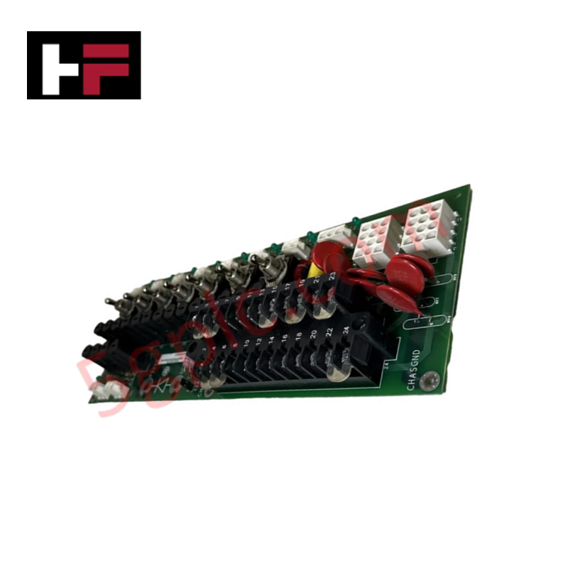
Configured for power distribution within the EX2100 Excitation Control system, the General Electric IS200EPDMG1B (IS200EPDMG1B Power Distribution Board) provides direct physical/electrical execution of voltage regulation for exciter control, I/O, and protection modules..
Hardware Specifications
| Parameter | Specification |
|---|---|
| Model | IS200EPDMG1B |
| Brand | General Electric |
| Origin | United States (USA) |
| Input Configuration | 120 V ac (dual) and 125 V dc station battery |
| Output Voltage | Nominal +62.5 V dc and -62.5 V dc (center grounded) |
| Mounting | Exciter Power Backplane (EPBP) |
Industrial Control and Firmware Integration
The IS200EPDMG1B operates within the EX2100 platform to provide standardized power distribution across the excitation control bus. The module manages the conversion and filtering of multi-source power inputs, including station batteries and rectified AC sources (DACA), to maintain stable P125V and R125V rails. Integration involves direct mechanical coupling to the EPBP backplane, where electrical connections are established for high-density power distribution. The system relies on deterministic power delivery to sustain the operation of protection boards and control I/O, requiring verification of board-level voltage tolerances to ensure compatibility with the excitation control software.
Frequently Asked Questions (FAQ)
Q: Can the IS200EPDMG1B accept simultaneous AC and DC power inputs?
A: Yes, the board is engineered to accept inputs from both 120 V ac sources and the 125 V dc station battery, utilizing internal and external diode logic to provide stable supply voltages.
Q: How is the output voltage potential referenced?
A: The P125V and R125V dc outputs are center-grounded, providing a nominal potential of +62.5 V dc and -62.5 V dc relative to the system ground.
Field Installation Guidelines
- Backplane Mounting: Align the board precisely with the guide rails on the Exciter Power Backplane (EPBP). Ensure connectors are fully seated to prevent intermittent contact and potential voltage fluctuations.
- Terminal Block Wiring: All power supply inputs must be terminated at TB1. Use appropriate wire gauges for 120 V ac and 125 V dc inputs to handle current loads. Tighten terminal screws to manufacturer-specified torque settings.
- Shielding and Grounding: Given the sensitivity of the excitation control system, ensure the center ground is properly bonded to the system earth bus. Verify that all input leads are properly shielded to minimize electromagnetic interference (EMI).
- Pre-Power Verification: Before applying input power, utilize a multimeter to verify the absence of shorts between the P125V/R125V rails and the system ground. Ensure external rectifier (DACA) outputs are correctly phased.
Additional Information
- 100% Genuine Parts: All products are original and authentic, ensuring reliable industrial performance.
- 30-Day Refund Guarantee: Return any in-stock item within 30 days in original, unopened packaging for a full refund (excluding shipping and fees).
- 12-Month Warranty: Covers defects in materials or workmanship; excludes misuse, normal wear, or unauthorized modifications.
- Worldwide Shipping: We ship via USPS, UPS, FedEx, and DHL. Delivery times vary by country and may be subject to customs or import fees.
- Support & Contact: Technical and warranty assistance is available anytime. Contact us here: Contact.
- Purchase Guidance: Check product specifications and compatibility carefully before ordering to ensure proper application.


Tech & Buying Guide

Mastering the Factory Acceptance Test (FAT) for PLC Control Panels: An Expert Guide
The Factory Acceptance Test (FAT) is a vital milestone in industrial automation that ensures custom PLC panels meet exact design specifications before dispatch. This guide outlines the step-by-step FAT procedure and key industry best practices to prevent costly site delays and ensure long-term operational success.

Redundant Automation Systems: Ensuring Continuous Uptime in Critical Control Infrastructure
System reliability directly determines operational profitability across high stakes process industries. Modern industrial automation platforms must eliminate single points of failure to prevent catastrophic shutdowns. Deploying fault tolerant architecture safeguards complex facilities against unexpected hardware glitches, network disruptions, and maintenance outages.

Understanding Types of Noise in Electronic Circuits and Control Systems
Signal integrity directly determines measurement accuracy and loop stability across industrial automation environments. Electronic noise introduces unwanted stochastic interference into analog loops, sensor feedback lines, and digital fieldbus networks. Understanding how intrinsic electronic noise and external electromagnetic interference manifest allows control engineers to optimize signal conditioning and shield sensitive instrumentation effectively.