


Product Details
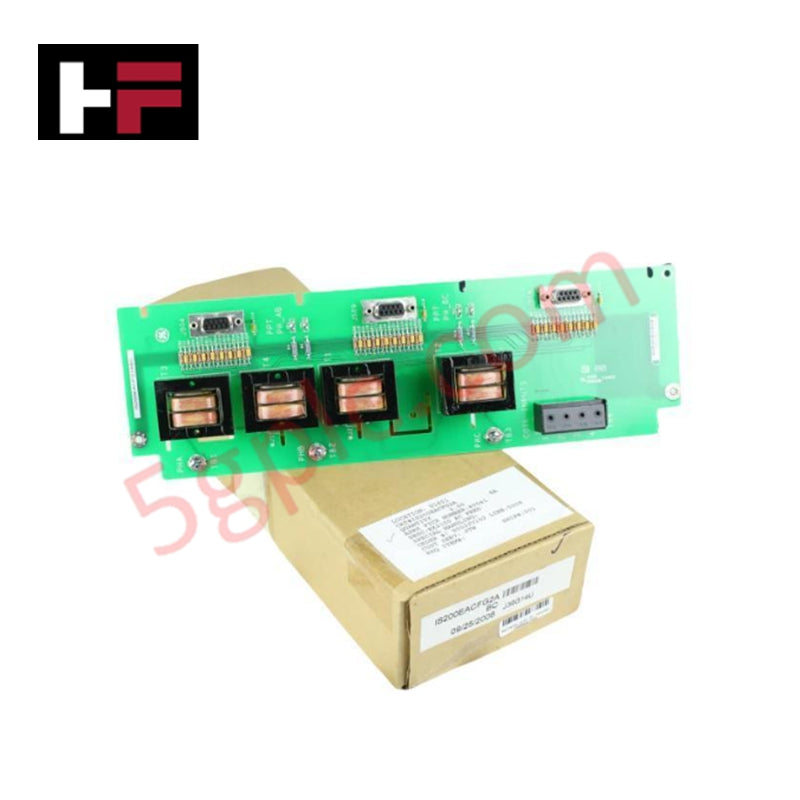
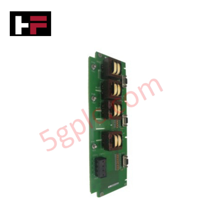
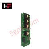
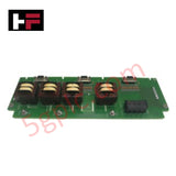
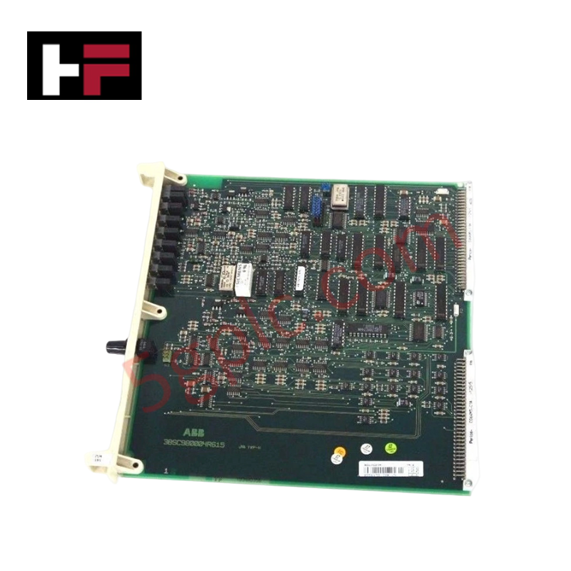
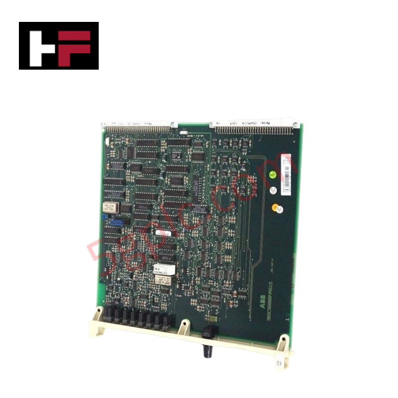
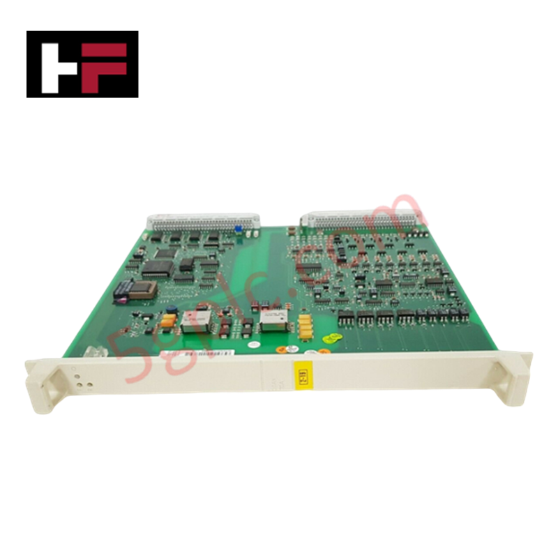
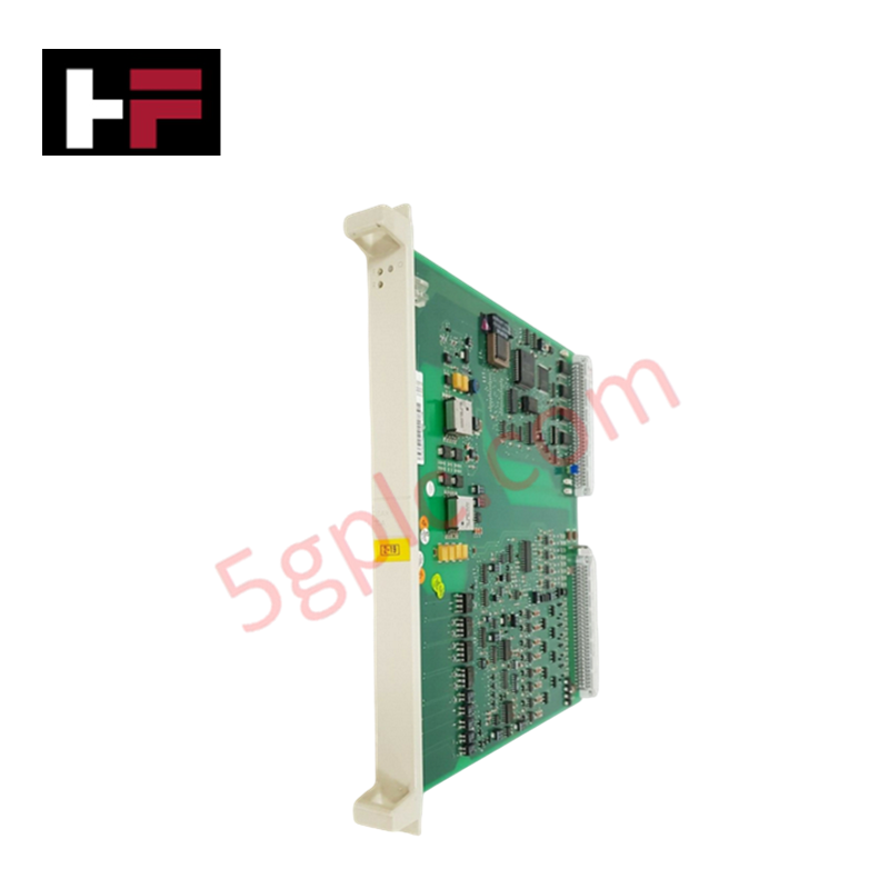
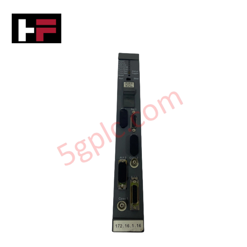
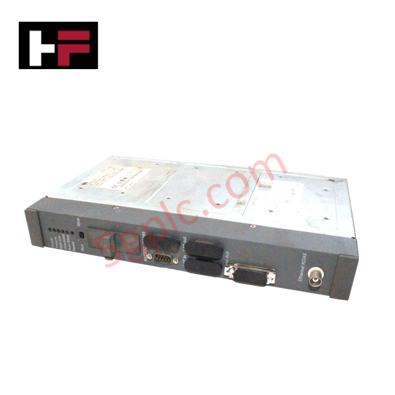
Configured for high-precision analog signal acquisition in Mark VIe excitation control systems, the General Electric IS200EACFG2ABB (IS200EACFG2ABB Exciter AC Feedback Board) provides direct physical/electrical execution of voltage monitoring and feedback conditioning.
Suffix Breakdown & Model Matrix
| Model | Channels | Voltage Range | Redundancy |
|---|---|---|---|
| IS200EACFG1A | 8 analog inputs | 24 V DC | Not supported |
| IS200EACFG2ABB | 16 analog inputs | 24 V DC | Supported |
| IS200EACFG3B | 32 analog inputs | 48 V DC | Supported |
Hardware Specifications
| Parameter | Specification |
|---|---|
| Model | IS200EACFG2ABB |
| Brand | General Electric |
| Analog Inputs | 16 |
| Voltage Input | 24 V DC |
| Configuration | Redundant support |
Profinet and Deterministic Network Operations
The IS200EACFG2ABB integrates into the Mark VIe control architecture via deterministic network interfaces to ensure synchronized signal polling. The module firmware flash compatibility allows for internal logic updates to maintain alignment with system-wide timing protocols. I/O density scaling is achieved through the board's 16-channel analog input array, which supports redundant configurations to prevent single-point signal failure. Backplane bus communication velocity is optimized for high-speed data transmission, ensuring that voltage feedback is available for control loop processing within defined deterministic windows.
Frequently Asked Questions (FAQ)
Q: Can the IS200EACFG2ABB be used in redundant control system configurations?
A: Yes, this model is specifically engineered to support redundant system configurations, providing higher availability for critical excitation control loops compared to the G1A variant.
Q: Is the input voltage range of the IS200EACFG2ABB compatible with the IS200EACFG3B?
A: No, the IS200EACFG2ABB is designed for 24 V DC input circuits, whereas the IS200EACFG3B is designed for 48 V DC applications. Ensure the field voltage matches the module specification during installation.
Field Installation Guidelines
- Mounting: Secure the board within the control cabinet to ensure proper alignment with backplane connectors. Verify that the module is fully seated to maintain reliable backplane communication.
- Signal Wiring: Connect analog input signals to the appropriate terminals. Use shielded, twisted-pair cabling to minimize common-mode noise and maintain the accuracy of the analog signal processing.
- Grounding: Bond the module chassis to the system reference ground. Proper grounding is necessary to maintain the integrity of the analog input channels and to prevent ground loop interference in the feedback path.
- Verification: After installation, utilize the system configuration tool to verify that all 16 analog channels are correctly mapped and reporting valid voltage data to the controller.
Additional Information
- 100% Genuine Parts: All products are original and authentic, ensuring reliable industrial performance.
- 30-Day Refund Guarantee: Return any in-stock item within 30 days in original, unopened packaging for a full refund (excluding shipping and fees).
- 12-Month Warranty: Covers defects in materials or workmanship; excludes misuse, normal wear, or unauthorized modifications.
- Worldwide Shipping: We ship via USPS, UPS, FedEx, and DHL. Delivery times vary by country and may be subject to customs or import fees.
- Support & Contact: Technical and warranty assistance is available anytime. Contact us here: Contact.
- Purchase Guidance: Check product specifications and compatibility carefully before ordering to ensure proper application.

Tech & Buying Guide

Mastering the Factory Acceptance Test (FAT) for PLC Control Panels: An Expert Guide
The Factory Acceptance Test (FAT) is a vital milestone in industrial automation that ensures custom PLC panels meet exact design specifications before dispatch. This guide outlines the step-by-step FAT procedure and key industry best practices to prevent costly site delays and ensure long-term operational success.

Redundant Automation Systems: Ensuring Continuous Uptime in Critical Control Infrastructure
System reliability directly determines operational profitability across high stakes process industries. Modern industrial automation platforms must eliminate single points of failure to prevent catastrophic shutdowns. Deploying fault tolerant architecture safeguards complex facilities against unexpected hardware glitches, network disruptions, and maintenance outages.

Understanding Types of Noise in Electronic Circuits and Control Systems
Signal integrity directly determines measurement accuracy and loop stability across industrial automation environments. Electronic noise introduces unwanted stochastic interference into analog loops, sensor feedback lines, and digital fieldbus networks. Understanding how intrinsic electronic noise and external electromagnetic interference manifest allows control engineers to optimize signal conditioning and shield sensitive instrumentation effectively.