


Product Details
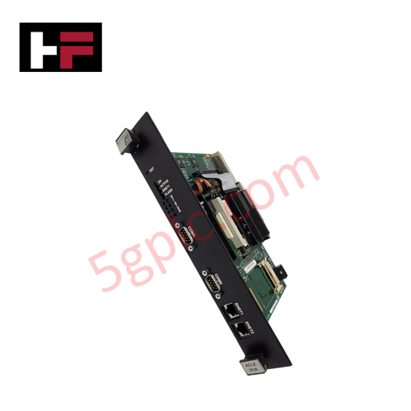
The General Electric IS200ACLEH1A, also cataloged as the IS200ACLEH1A Application Control Layer Module, operates as a dedicated hardware component for microprocessor-based master control and network communication processing within EX2100 excitation control system platforms.
Hardware Specifications
| Parameter | Specification |
|---|---|
| Model | IS200ACLEH1A |
| Brand | General Electric |
| Origin | United States (USA) |
| Dimensions | Occupies two rack slots |
| Processor Type | Microprocessor-based |
| PCB Coating | Conformal coating |
| Configuration Tool | GE Control System Toolbox |
Industrial Control and Firmware Integration
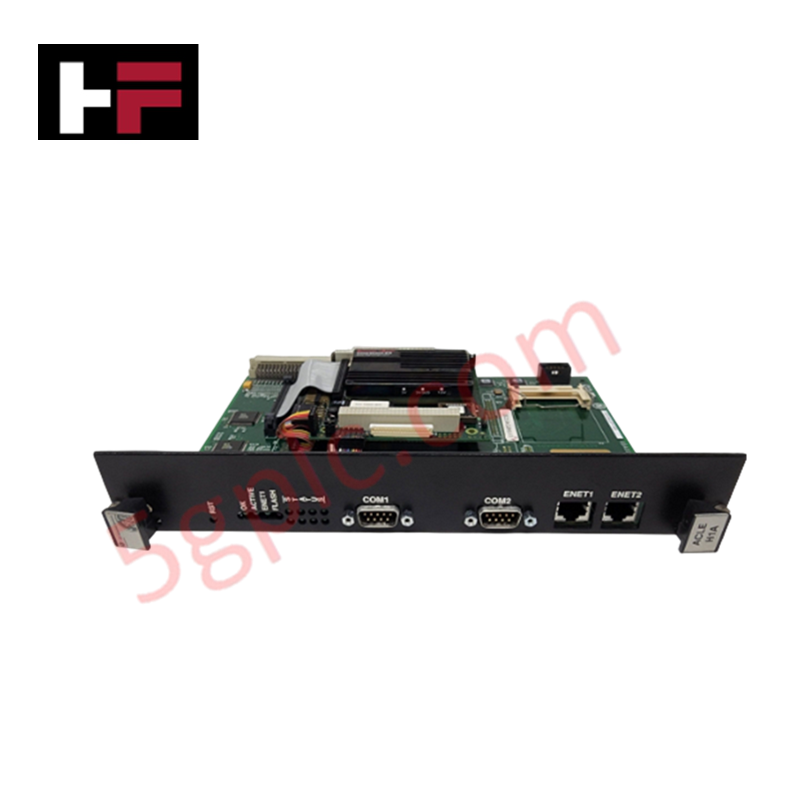
The IS200ACLEH1A utilizes deterministic network protocols, including Ethernet, to execute concurrent control tasks. The module requires firmware flash compatibility to support the onboard software and configuration loading managed via the GE Control System Toolbox. The module architecture features I/O density scaling capabilities, allowing it to interface with backplane connectors and auxiliary boards while maintaining scan-time synchronization across the EX2100 exciter rack. Its status LEDs provide real-time monitoring of internal firmware processes, including watchdog timer activity, memory access, and flash memory write operations.
Frequently Asked Questions (FAQ)
Q: What is the physical footprint of the IS200ACLEH1A module?
A: Due to its wide faceplate design, this module occupies two slots within the EX2100 Excitation Control System Rack.
Q: What is the purpose of the conformal PCB coating applied to this module?
A: The conformal coating consists of a thin layer of chemical protection applied to the circuit board surface to enhance resistance to environmental contaminants and atmospheric conditions.
Field Installation Guidelines
- Rack Placement: Ensure the module is aligned with the rack guide rails before engaging the backplane connector. Since the unit occupies two slots, verify adjacent slot availability and rack clearance.
- Connector Engagement: Confirm that the vertical male pin connector, backplane connector, and the multi-pin ribbon cable connector are fully seated. Ensure the ribbon cable connecting to the auxiliary board is free of kinks or tension.
- Grounding: Secure the module faceplate screws to the rack frame to establish a proper chassis ground, which is necessary for shielding the sensitive microprocessor and memory components.
- ESD Precautions: Utilize a standard anti-static wrist strap during installation. The board contains integrated circuits and an IDE-to-SATA converter that are sensitive to electrostatic discharge.
- Verification: Following installation, power the system and observe the faceplate LEDs. A stable "OK" LED indicates the watchdog timer is enabled, while the "ENET" LED confirms established Ethernet communication activity.
Additional Information
- 100% Genuine Parts: All products are original and authentic, ensuring reliable industrial performance.
- 30-Day Refund Guarantee: Return any in-stock item within 30 days in original, unopened packaging for a full refund (excluding shipping and fees).
- 12-Month Warranty: Covers defects in materials or workmanship; excludes misuse, normal wear, or unauthorized modifications.
- Worldwide Shipping: We ship via USPS, UPS, FedEx, and DHL. Delivery times vary by country and may be subject to customs or import fees.
- Support & Contact: Technical and warranty assistance is available anytime. Contact us here: Contact.
- Purchase Guidance: Check product specifications and compatibility carefully before ordering to ensure proper application.


Tech & Buying Guide

Understanding Dry Contacts in PLC Wiring: An Industrial Automation Guide
Mastering contact switching principles is essential for reliable control panels. Field devices and PLCs interface through dry or wet contacts. This technical guide examines the mechanics of dry contacts, explores their wiring architectures, and evaluates their key advantages in industrial automation.

Ultimate Commissioning Checklist for Industrial Automation Systems: An Engineering Guide
Commissioning is the most decisive phase of an industrial automation project, transforming control hardware and software into an operational facility. Thorough testing prevents costly startup delays and builds customer confidence. This guide covers essential checklists, electrical standards, and best practices.

Redundant Automation Systems: Core Architecture, Business Value, and Technical Advantages
Unplanned downtime poses a major financial threat to process manufacturing. To prevent costly interruptions, engineers deploy redundant PLC and DCS architectures that ensure continuous operation when hardware fails. This technical guide explores redundancy principles, critical system nodes, and real-world scenarios.