


Product Details
Product Description
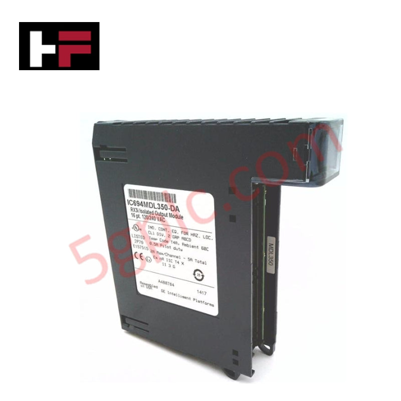
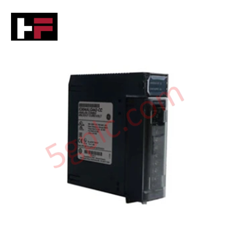
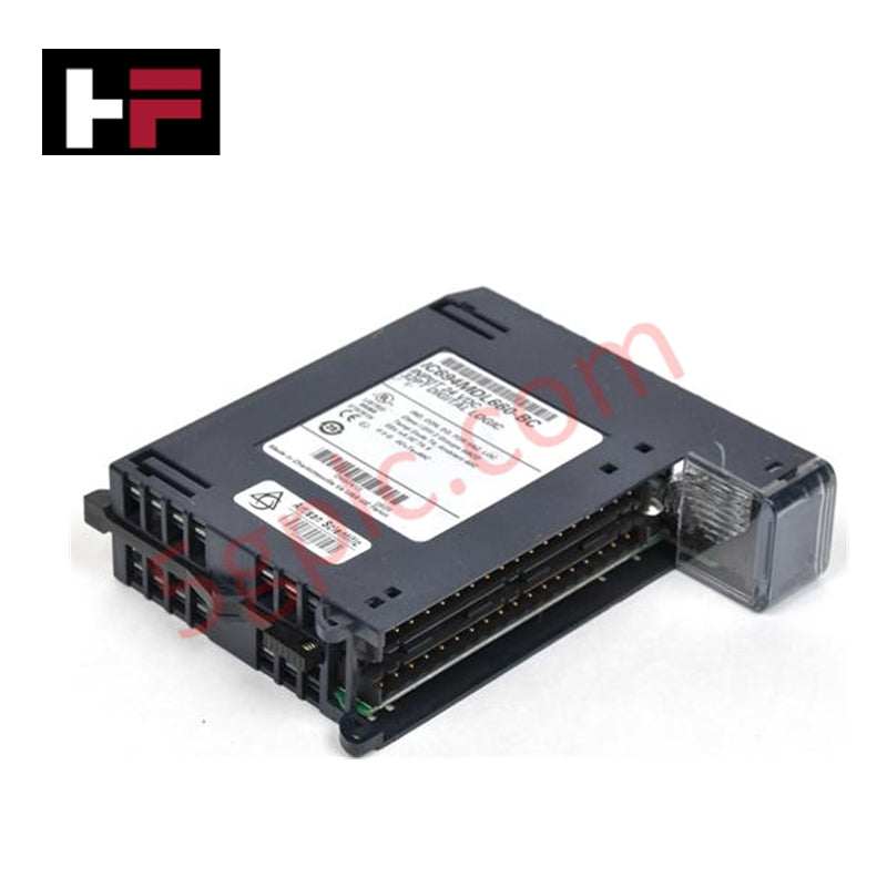
The IC694ALG392 analog output module from GE Fanuc PACSystems RX3i series provides eight channels of precise voltage and current outputs for process control and automation systems. Designed for reliable signal generation, it supports both 0–10 VDC and 0–20 mA ranges, with fast update rates to ensure accurate response in demanding applications.
Technical Specifications
-
Manufacturer: GE Fanuc Emerson
-
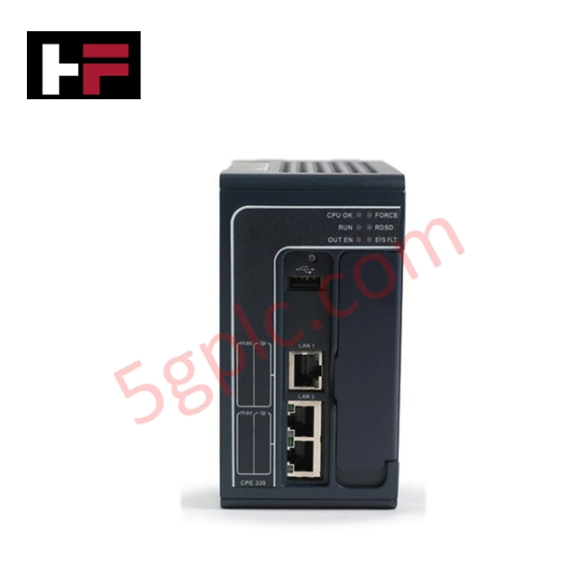
Product Line: PACSystems RX3i
-
Part Number: IC694ALG392
-
Product Type: Analog Output Module
-
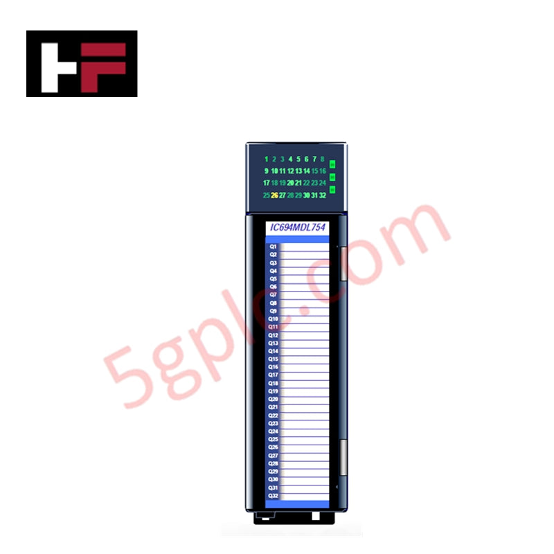
Number of Channels: 8 analog outputs
-
Supply Voltage: 24 VDC
-
Voltage Output Range: 0–10 VDC
-
Current Output Range: 0–20 mA
-
Update Rate: 8 ms for all channels
-
Accuracy: ±0.5% of full scale (typical)
-
Category: PLCs / Machine Control
-
Category: PLC Module / Rack
-
Weight: 0.66 lbs (0.30 kg)
-
Lifecycle Status: Active
Application Scenarios
-
Process industries requiring precise analog signal generation
-
Machine control systems needing multiple voltage and current outputs
-
Automation environments where fast update rates are critical
FAQ
Q: How many analog outputs are available? A: 8 channels.
Q: What signal ranges are supported? A: 0–10 VDC for voltage and 0–20 mA for current.
Q: What is the update rate? A: 8 milliseconds for all channels.
Q: What is the supply voltage required? A: 24 VDC.
Additional Information
- 100% Genuine Parts: All products are original and authentic, ensuring reliable industrial performance.
- 30-Day Refund Guarantee: Return any in-stock item within 30 days in original, unopened packaging for a full refund (excluding shipping and fees).
- 12-Month Warranty: Covers defects in materials or workmanship; excludes misuse, normal wear, or unauthorized modifications.
- Worldwide Shipping: We ship via USPS, UPS, FedEx, and DHL. Delivery times vary by country and may be subject to customs or import fees.
- Support & Contact: Technical and warranty assistance is available anytime. Contact us here: Contact.
- Purchase Guidance: Check product specifications and compatibility carefully before ordering to ensure proper application.


Tech & Buying Guide

Preventing Spurious Trips in Emergency Stop Systems: A Technical Guide
In industrial automation, the Emergency Stop (E-Stop) pushbutton is the ultimate safety line. However, relying on a single Normally-Closed (NC) contact can sometimes lead to unexpected spurious trips. As a control systems engineer, I have seen these nuisance trips halt entire production lines, causing significant downtime. Understanding why these components fail and how to implement robust architecture is essential for any reliable DCS or PLC-based safety system.

Sequencing Induction Motor Control with PLC Logic: Best Practices
In modern industrial automation, controlling a group of induction motors requires precision and safety. Uncontrolled simultaneous startup of multiple large motors often causes significant voltage dips, potentially triggering protective trips. Therefore, implementing a sequential startup and shutdown strategy is essential. This approach minimizes inrush current and ensures the system operates within established power constraints. A robust PLC program serves as the ideal engine for orchestrating these sequences.

Mastering PLC Programming: Best Practices for Robust Industrial Automation
Writing clean PLC code requires discipline, especially regarding memory management. Avoid overusing SET and RESET instructions, as they often complicate debugging. If multiple rungs control the same bit, troubleshooting becomes a nightmare. Instead, focus on energizing a bit in only one location. If your logic requires complex conditions, use branches within a single rung. This approach keeps your code readable, maintainable, and significantly easier to audit during downtime.