










Product Details
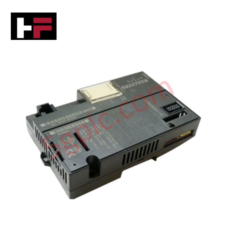
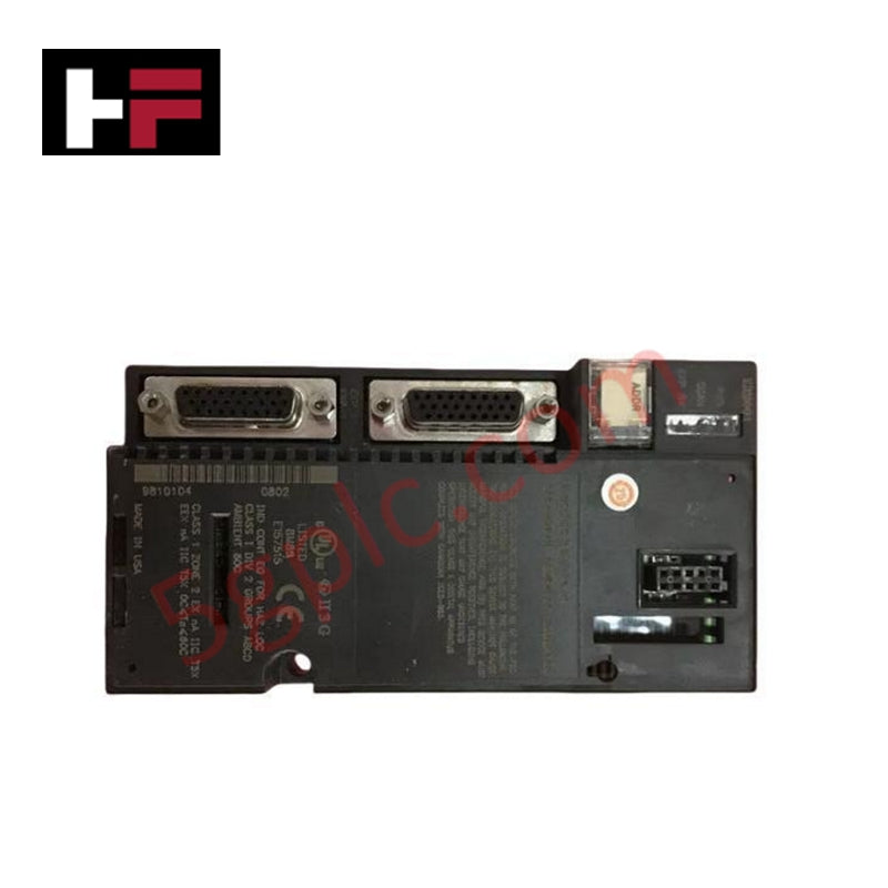
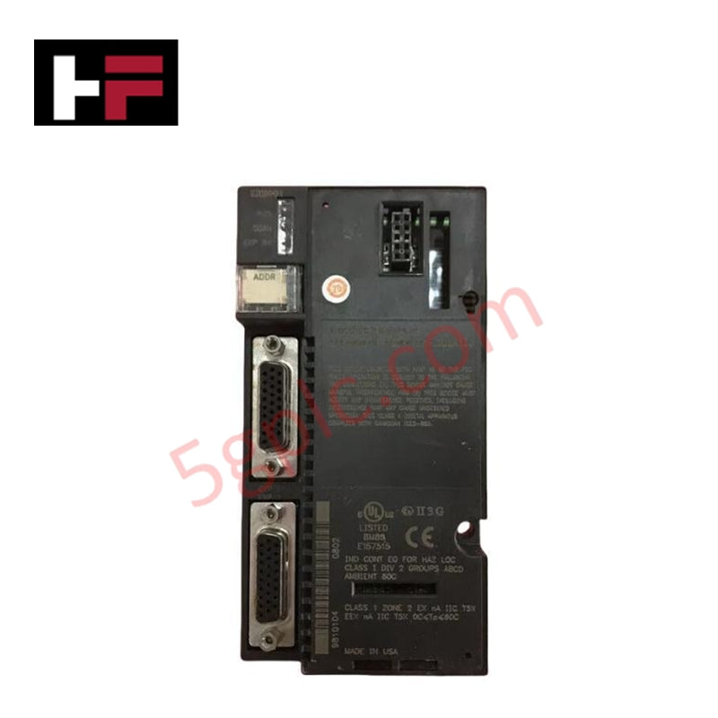
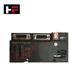
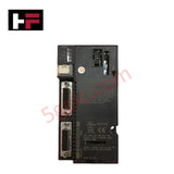
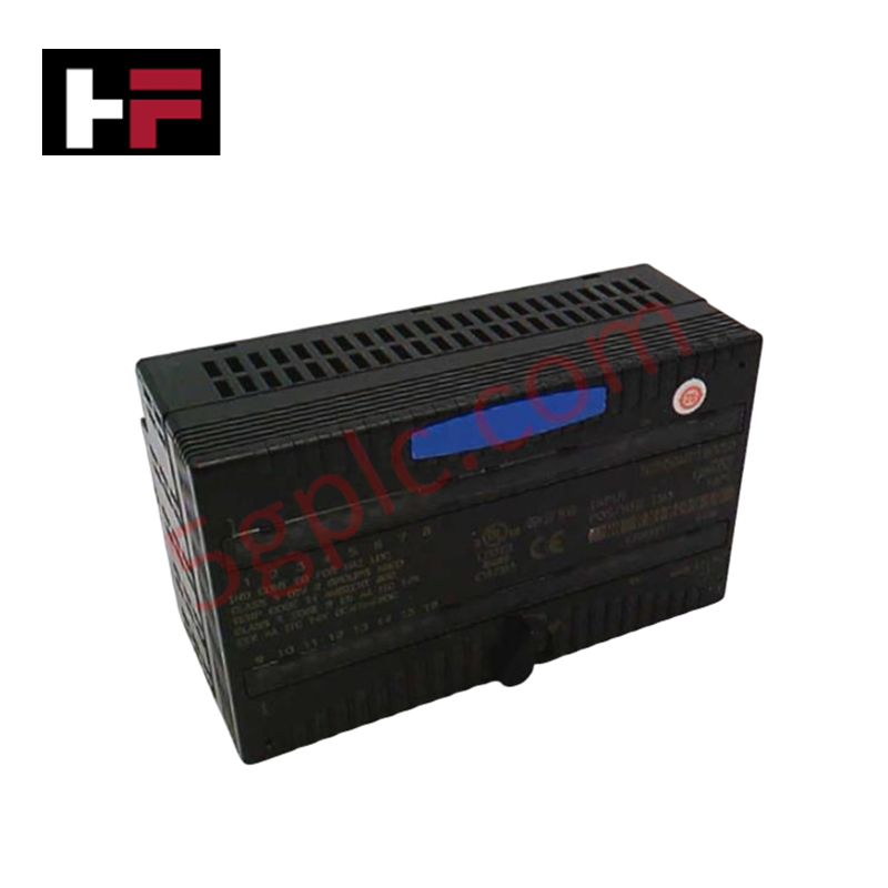
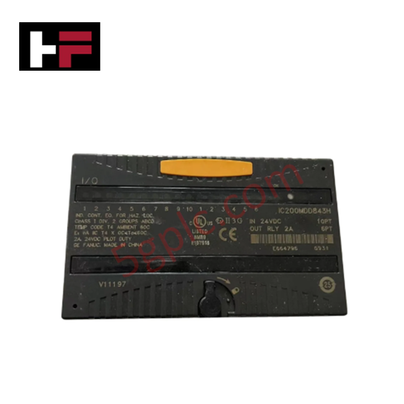
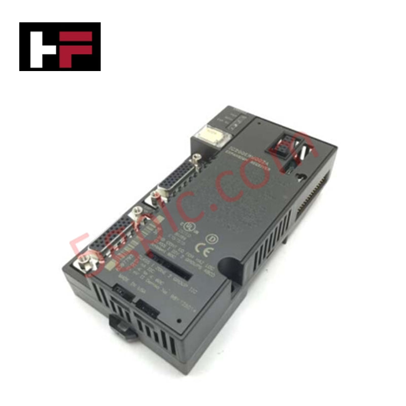
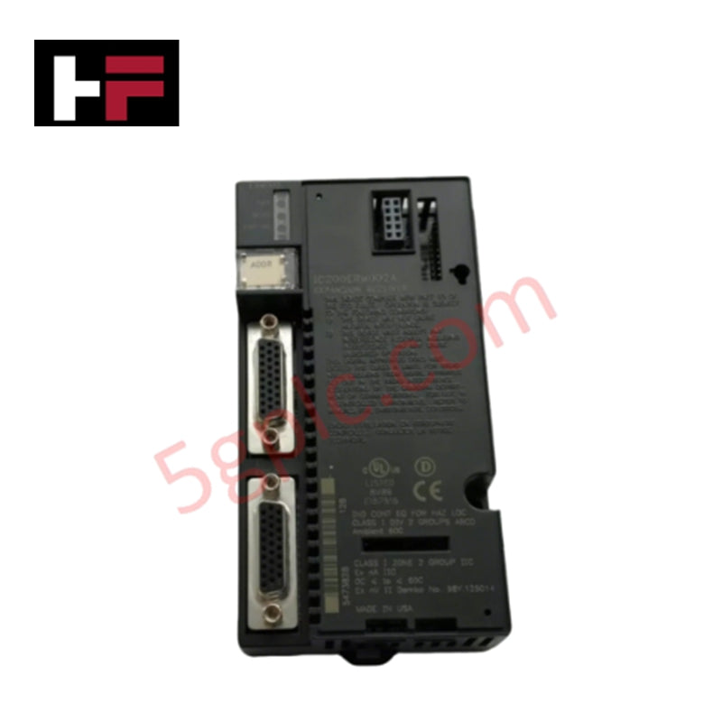
The GE IC200ERM001C, also cataloged as the IC200ERM001 Isolated Expansion Receiver Module, operates as a dedicated hardware component for multi-rack I/O bus expansion and signal isolation within GE VersaMax control platforms.
Hardware Specifications
| Parameter | Specification |
|---|---|
| Model | IC200ERM001C |
| Brand | GE (GE Fanuc / Emerson) |
| Origin | USA |
| Weight | 0.23 kg (0.50 lbs) |
| Power Consumption | Power sourced via backplane power supply |
| Max Backplane Output Voltage | 5 VDC |
| Min Backplane Output Voltage | 3.3 VDC |
| Expansion Connectors | 2 female 26-pin D-shell ports |
| Rack ID Selection | Onboard rotary switch |
| Status Indicators | LEDs for Power Status and Expansion Bus Status |
| Mounting Location | Far-left slot on VersaMax expansion rack DIN rail |
Backplane Bus Communication Velocity & Deterministic Network Execution
The IC200ERM001C receives isolated expansion bus signals from an upstream expansion transmitter module (such as the ETM001) via its top 26-pin D-shell port. It rebuilds and routes local backplane voltage levels between 3.3 VDC and 5 VDC to power downstream I/O and communication modules installed on the expansion rack, optimizing backplane bus communication velocity across long distances.
The bottom female 26-pin D-shell port enables daisy-chain connections to subsequent expansion racks or accommodates an expansion bus terminator plug on the final node. Full integration into Profinet / EtherNet/IP deterministic network topologies is maintained through the primary controller interface, while strict firmware flash compatibility ensures synchronized scan execution and low-latency protocol passthrough across all extended racks.
Frequently Asked Questions
Q: What is the functional role of the rotary switch located on the IC200ERM001C module?
A: The rotary switch located under the front access door sets the unique hardware address (Rack ID) for the specific expansion rack within the system topology.
Q: How are the two 26-pin female D-shell ports utilized on the expansion receiver module?
A: The top D-shell port receives the expansion cable from the upstream transmitter or preceding receiver, while the bottom port daisy-chains to the next expansion rack or houses a bus termination plug on the final rack.
Q: Can the IC200ERM001C module be removed or inserted while the expansion rack power supply is energized?
A: No. All incoming power sources to the expansion rack and primary controller must be de-energized prior to removing or installing the module to prevent electrical damage to the expansion bus.
Field Installation Guidelines
- Power Shutdown: De-energize and lock out all power sources feeding the host system and the expansion rack backplane prior to installation or maintenance.
- Rack Position: Mount the IC200ERM001C module exclusively in the far-left slot position of the VersaMax expansion rack on the 35 mm DIN rail.
- Address Configuration: Set the onboard rotary switch to the assigned expansion rack ID number prior to securing the module onto the backplane carrier.
- Cable Interconnection: Secure the 26-pin expansion cable from the upstream transmitter into the top D-shell port using integrated thumbscrews. Attach a daisy-chain cable or terminal plug to the bottom D-shell port.
- Electrostatic Discharge (ESD): Wear a grounded anti-static wrist strap attached to the enclosure metallic earth during installation to protect onboard IC logic from static damage.
Additional Information
- 100% Genuine Parts: All products are original and authentic, ensuring reliable industrial performance.
- 30-Day Refund Guarantee: Return any in-stock item within 30 days in original, unopened packaging for a full refund (excluding shipping and fees).
- 12-Month Warranty: Covers defects in materials or workmanship; excludes misuse, normal wear, or unauthorized modifications.
- Worldwide Shipping: We ship via USPS, UPS, FedEx, and DHL. Delivery times vary by country and may be subject to customs or import fees.
- Support & Contact: Technical and warranty assistance is available anytime. Contact us here: Contact.
- Purchase Guidance: Check product specifications and compatibility carefully before ordering to ensure proper application.
Tech & Buying Guide

Comprehensive Guide to PLC Types in Modern Industrial Automation
Modern industrial automation relies on programmable logic controllers to govern critical factory operations. System integrators classify PLCs based on scale, hardware architecture, and power supply design. Understanding these core categories enables automation engineers to select the right control system architecture. Consequently, proper hardware selection optimizes performance while minimizing long-term operational costs.

Demystifying the DDE Protocol in Legacy Industrial Automation Systems
Modern control systems rely heavily on seamless interprocess communication to exchange operational data between software programs. Microsoft first introduced the Dynamic Data Exchange (DDE) protocol in 1987 to enable real-time data sharing. In factory automation, DDE served as an early bridge between control software and Windows desktop applications. Therefore, understanding DDE mechanics provides crucial insights into how legacy industrial networks established software-level connectivity.

Demystifying CPU Communication Ports in Siemens PLC Architectures
Industrial automation relies heavily on robust data exchange between devices. Without seamless connectivity, field instruments, network switches, human-machine interfaces, and programmable logic controllers cannot coordinate effectively. Therefore, understanding the various CPU communication ports available in Siemens hardware ensures efficient factory automation design and seamless system integration.