










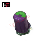
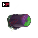
Product Details
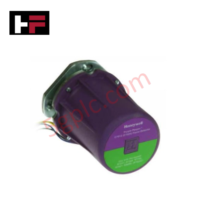
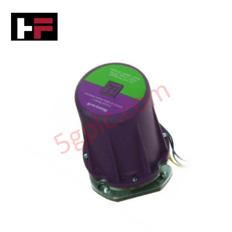
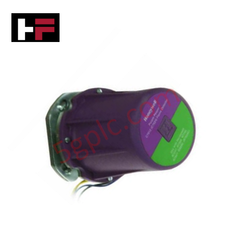
Configured for dynamic self-check flame supervision in industrial burner management systems, the Honeywell C7061A1079 (C7061A UV Flame Detector) provides direct physical/electrical execution of ultraviolet radiation sensing across process heating platforms.
Hardware Specifications
| Parameter | Specification |
| Model | C7061A1079 |
| Brand | Honeywell |
| Origin | USA |
| Weight | 1.0 lbs (0.45 kg) |
| Dimensions | Standard C7061 Housing Assembly |
| Operating Temp | -40 deg C to +70 deg C (-40 deg F to +160 deg F) |
| Power Consumption | Operating Voltage 120/230 VAC, 50/60 Hz |
| Sensor Type | Solid-state UV tube |
| Self-Check Frequency | Dynamic shutter cycle, minimum 1 cycle/min |
| Viewing Window | Field-replaceable Quartz lens |
| Wiring Connections | 8 ft (2.4 m) color-coded lead wires |
| Mechanical Mounting | 3/4 in NPT threaded flange |
| Enclosure Protection | NEMA 4 / IP66 weatherproof rating |
Dynamic Self-Checking and Signal Isolation
The C7061A1079 incorporates an internal electromechanical shutter mechanism driven by dual shutter coil circuitry compatible with 120/230 VAC systems. The shutter interrupts the optical path to the solid-state UV tube at least once per minute, simulating a flame failure state to verify tube response and electronic circuit integrity without stopping burner operation. Integrated optical filtering isolates ultraviolet radiation bands emitted by hydrocarbon combustion while ignoring ambient infrared radiation and hot refractory wall emissions. Signal output conditioning prevents transient electromagnetic interference from disrupting high-speed burner safety shutdown channels.
Frequently Asked Questions
Q: What is the primary purpose of the internal dynamic self-checking shutter mechanism in the C7061A1079?
A: The shutter interrupts the ultraviolet radiation path to the UV sensor tube periodically to verify that the sensor tube and internal amplifier circuits respond to a simulated flame-out condition, preventing runaway failure modes in continuous-firing burners.
Q: How is the viewing lens maintained or replaced if contaminated by process particulate?
A: The front housing contains a threaded retaining assembly holding a quartz viewing window. Main AC supply power must be isolated prior to unthreading the sight pipe fitting to access, clean, or replace the quartz lens without removing the entire detector enclosure.
Q: Can the C7061A1079 be wired directly to standard safety shutdown controllers over long distances?
A: Yes, the module includes an 8 ft (2.4 m) color-coded lead wire assembly. When extending lead wire runs to remote control panels, standard industrial shielded twisted-pair cables must be used with proper conduit isolation to prevent high-voltage crosstalk.
Field Installation Guidelines
-
Thread the 3/4 in NPT mechanical flange onto a clean sight pipe aimed directly at the intersection of the primary flame envelope and the burner firing head.
-
Ensure sight pipe engagement maintains at least 5 full NPT thread turns to satisfy structural mounting requirements and pressure sealing.
-
Route the 8 ft color-coded lead wires through dedicated grounded metal conduit separate from ignition transformer leads and high-voltage AC power lines.
-
Verify that ambient temperatures at the housing location remain between -40 deg C and +70 deg C; install auxiliary sight pipe cooling air systems if radiant heat exceeds maximum ratings.
Additional Information
- 100% Genuine Parts: All products are original and authentic, ensuring reliable industrial performance.
- 30-Day Refund Guarantee: Return any in-stock item within 30 days in original, unopened packaging for a full refund (excluding shipping and fees).
- 12-Month Warranty: Covers defects in materials or workmanship; excludes misuse, normal wear, or unauthorized modifications.
- Worldwide Shipping: We ship via USPS, UPS, FedEx, and DHL. Delivery times vary by country and may be subject to customs or import fees.
- Support & Contact: Technical and warranty assistance is available anytime. Contact us here: Contact.
- Purchase Guidance: Check product specifications and compatibility carefully before ordering to ensure proper application.
Tech & Buying Guide

Comprehensive Guide to Instrumentation and Control (I&C) Design Basis
Instrumentation and Control (I&C) Design Basis serves as the foundational technical document for modern plant engineering. Project teams rely on this master specification to govern engineering deliverables across front-end engineering design (FEED) and detailed execution phases. A well-constructed I&C design basis ensures seamless integration among field instrumentation, safety systems, and main control systems. Furthermore, establishing clear technical standards early mitigates execution risks and prevents costly re-engineering during plant commissioning.

The Shift to Flexible IO Modules in Modern Industrial Automation
Traditional control systems rely on dedicated Input Output (IO) cards for industrial automation. Each conventional module processes a single signal type, such as Digital Input (DI), Digital Output (DO), Analog Input (AI), or Analog Output (AO). A standard 16-channel card accepts only one specific channel type across all ports. This inflexible hardware design often creates severe engineering bottlenecks during project execution. Engineers frequently must install entirely new cards to accommodate a single extra sensor. Consequently, late design changes increase control cabinet space requirements and drive up project costs.

DCS Commissioning Steps in Industrial Automation Projects
Commissioning a Distributed Control System (DCS) represents a crucial milestone when deploying modern process automation infrastructure. Field engineers must execute systematic verification steps to transition complex control hardware from static installation to dynamic plant control. Proper commissioning ensures that controllers, I/O modules, network switches, and HMI software operate in strict compliance with engineering design specifications before introducing live process fluids.