

Product Details
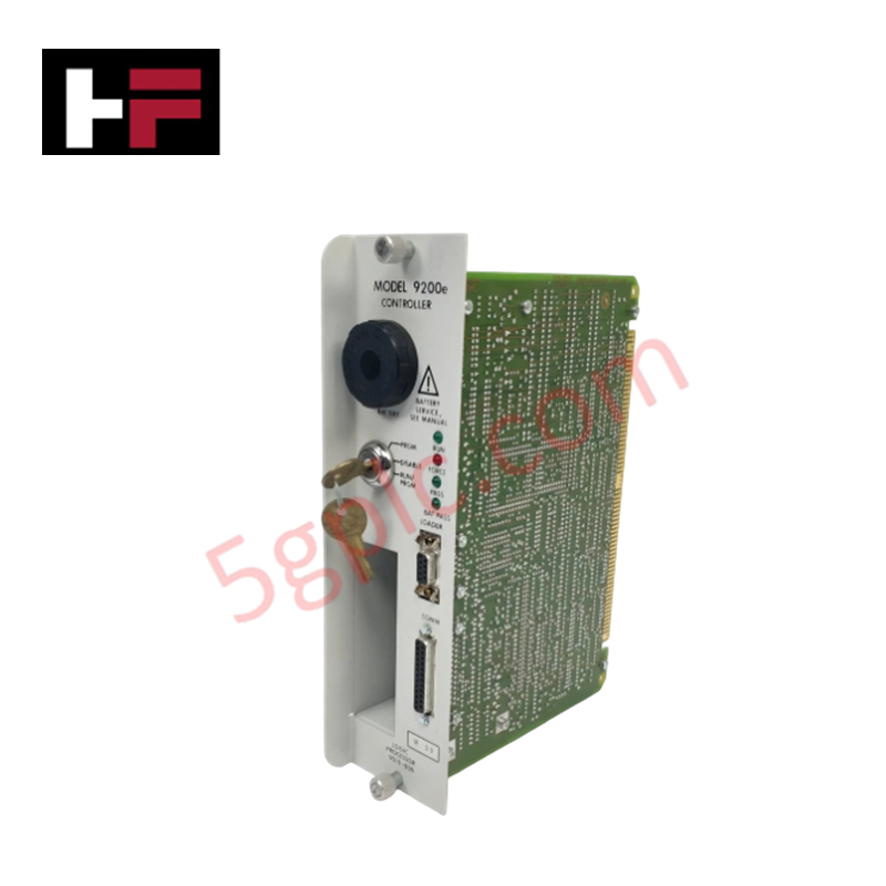
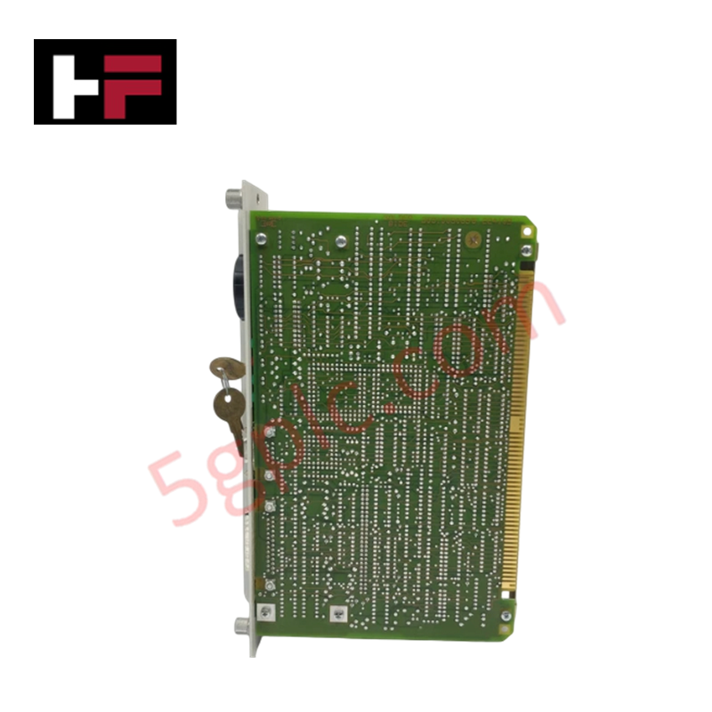
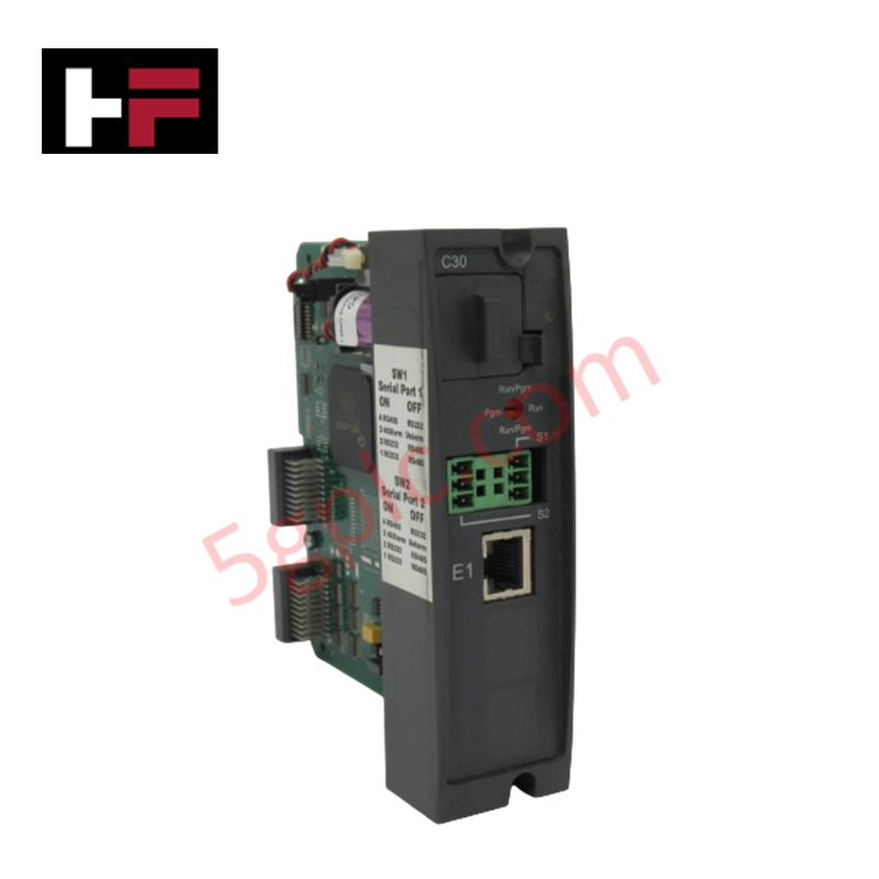
The Honeywell 9010-036, also cataloged as the 9010-036 Logic Processor Module, operates as a dedicated hardware component for high-speed logic execution and digital field signal processing within Honeywell 9200e process control platforms.
Hardware Specifications
| Parameter | Specification |
|---|---|
| Model | 9010-036 (Part Number: 508655-001) |
| Brand | Honeywell |
| Origin | USA / Global Manufacturing |
| Weight | 0.5 lbs (0.23 kg) |
| Dimensions | 9.5 x 2.5 x 0.75 inches |
| Operating Temp | 0 to +60 deg C |
| Power Consumption | Powered via Backplane Rail |
| Clock Speed | 10 MHz |
| Onboard Memory | 128 KB RAM |
| I/O Capacity | 16 Digital Inputs, 8 Digital Outputs |
4-20 mA HART Loop Protocol and Channel Isolation Conditioning
The 9010-036 logic processor module executes user-defined control logic sequentially at a 10 MHz clock rate, accessing its 128 KB RAM memory space to update system states and manage physical I/O channels. Designed for integration into Honeywell industrial architectures, the processor communicates directly across the system backplane to aggregate discrete input signals and update output channels.
When linked to multi-channel process loops, such as transmitters operating on 4-20 mA HART loop protocol configurations, the processing system relies on galvanic channel-to-channel isolation within associated analog I/O assemblies. This structure suppresses common-mode noise and prevents ground potential differentials from corrupting the internal bus execution or damaging board-level logic components.
Frequently Asked Questions
Q: What physical I/O channels are directly integrated into the 9010-036 hardware?
A: The module incorporates 16 digital input points and 8 digital output points on its physical interface connection.
Q: What clock speed and RAM memory capacity does the 9010-036 processor feature?
A: The processor runs on a 10 MHz system clock and contains 128 KB of onboard RAM for program execution and data buffering.
Q: Is hot-swapping permitted for the 9010-036 module during active backplane operation?
A: No, backplane power must be fully isolated and de-energized prior to inserting or removing the module assembly to prevent backplane bus transients.
Field Installation Guidelines
- Disconnect all rack power sources and field wiring lines prior to inserting or extracting the module.
- Utilize a grounded ESD wrist strap connected to the panel chassis during physical handling of the circuit board.
- Slide the module into the card cage slots until backplane pin connectors are fully seated before tightening retaining hardware.
- Route digital input/output field wiring separately from high-voltage AC cables to minimize electromagnetic coupling.
Additional Information
- 100% Genuine Parts: All products are original and authentic, ensuring reliable industrial performance.
- 30-Day Refund Guarantee: Return any in-stock item within 30 days in original, unopened packaging for a full refund (excluding shipping and fees).
- 12-Month Warranty: Covers defects in materials or workmanship; excludes misuse, normal wear, or unauthorized modifications.
- Worldwide Shipping: We ship via USPS, UPS, FedEx, and DHL. Delivery times vary by country and may be subject to customs or import fees.
- Support & Contact: Technical and warranty assistance is available anytime. Contact us here: Contact.
- Purchase Guidance: Check product specifications and compatibility carefully before ordering to ensure proper application.






Tech & Buying Guide

Voice-Activated Industrial Automation: Integrating Speech Control into PLC and DCS Architectures
Industrial automation integrates speech recognition, IIoT protocols, and NLP with PLCs and DCS to streamline operations. By leveraging advanced edge computing, engineers enable real-time, hands-free control—allowing personnel to manage smart factory processes safely away from hazardous equipment.
Modern Industrial Automation: Transforming Safety and Efficiency in Mining Operations
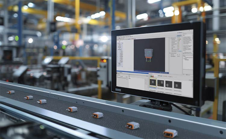
Industrial automation has evolved from a simple manufacturing tool into the operational backbone of high-risk sectors. Modern mining operations increasingly rely on advanced control systems, programmable logic controllers (PLCs), distributed control systems (DCS), and artificial intelligence to address deep-underground hazards. By replacing manual labor in high-risk zones, factory automation technologies protect personnel while significantly boosting operational throughput.