


Product Details
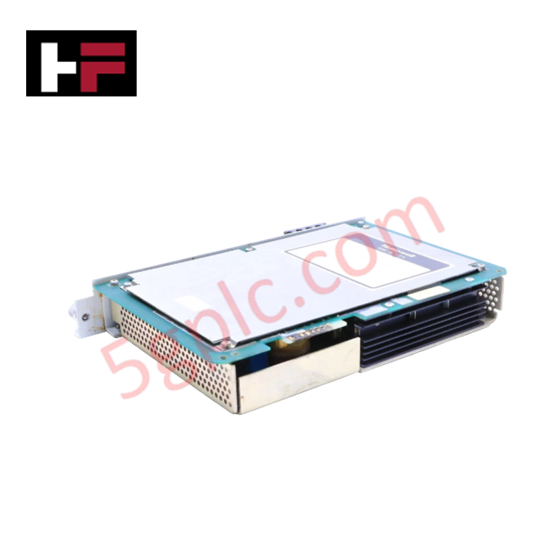
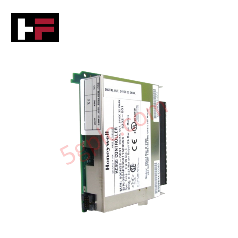
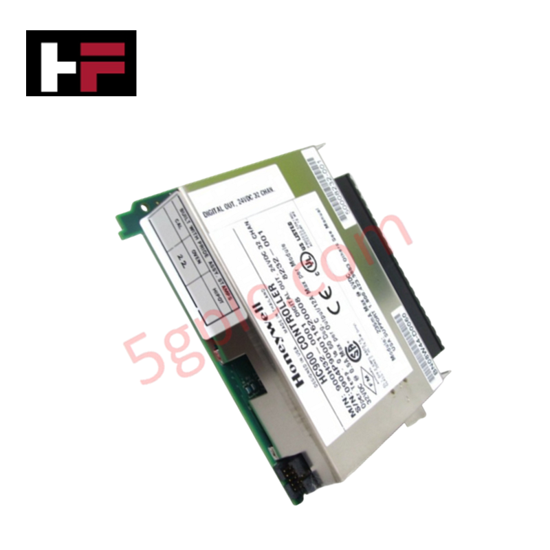
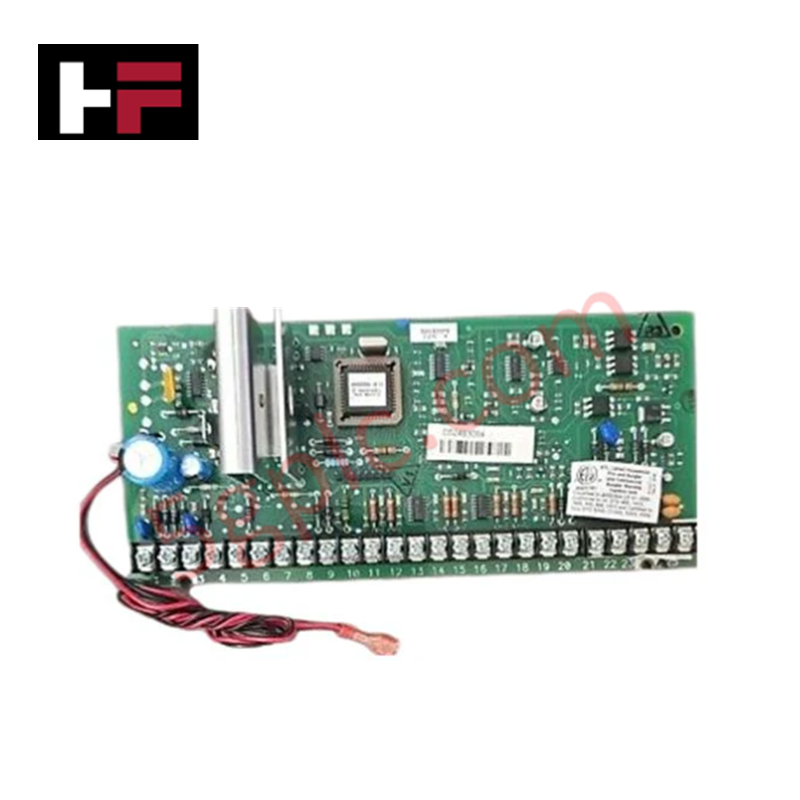
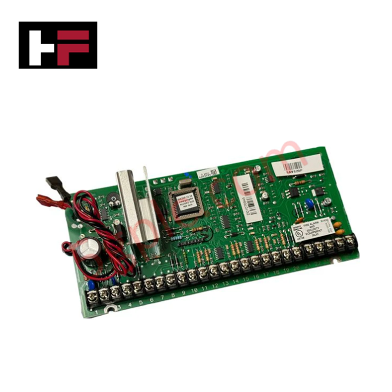
Configured for power distribution and communication management in IPC 620 controller networks, the Honeywell 621-9932 (621-9932 I/O Rack Power Supply Module) provides direct physical execution of voltage regulation for rack-mounted I/O modules. The module serves as the primary power interface utilized to execute status monitoring and voltage conversion across Honeywell IPC 620 control platforms.
Hardware Specifications
| Parameter | Specification |
|---|---|
| Model | 621-9932 |
| Brand | Honeywell |
| Origin | Not Specified |
| Weight | 2.27 kg |
| Dimensions | 45.72 x 35.56 x 30.48 cm |
| Input Voltage | 20-28 VDC |
| Output Power | 96 VA |
| Cold Start Surge | 40 A |
Process Control and Connectivity
The 621-9932 module maintains stable secondary voltages for the I/O backplane, facilitating data communication between the central controller and remote signal modules. To ensure integrity in 4-20 mA HART loop protocol loops, the supply provides filtered DC output, minimizing ripple that could introduce common-mode noise into analog measurement signals. The module incorporates channel-to-channel isolation on the output stage to contain localized electrical faults, preventing a short-circuit on a single I/O loop from collapsing the entire rack power rail. The front-accessible fuse holder permits protection against over-current conditions, ensuring that faults are isolated at the module level without interrupting the main DC bus.
Frequently Asked Questions
Q: Does the 621-9932 support hot-swapping in the IPC 620 rack?
A: No. The module is not designed for hot-swapping. Removal or installation while the rack backplane is energized will result in voltage transients that may trigger an I/O fault or cause unintended processor resets in the connected controller.
Q: Is the LED status indicator directly wired to the input voltage or the regulated output?
A: The LED status indicator monitors the regulated output state. A loss of illumination indicates a failure of the internal conversion circuitry, a tripped fuse, or the absence of primary 20-28 VDC input power.
Field Installation Guidelines
- Ensure the primary 20-28 VDC power source is isolated and locked out before initiating installation.
- Utilize the DIN-rail mounting feature to secure the module to the control panel backplane, ensuring a robust mechanical connection for vibration resistance.
- Terminate the input and output wiring in accordance with standard industrial practices, ensuring that current-carrying conductors are appropriately sized for the 96 VA output rating.
- Verify the integrity of the chassis ground connection to the DIN-rail to ensure effective EMI suppression and protection against surge events.
- Inspect the fuse holder and LED indicator status upon power-up to confirm the module is providing nominal output voltage to the I/O backplane.
Additional Information
- 100% Genuine Parts: All products are original and authentic, ensuring reliable industrial performance.
- 30-Day Refund Guarantee: Return any in-stock item within 30 days in original, unopened packaging for a full refund (excluding shipping and fees).
- 12-Month Warranty: Covers defects in materials or workmanship; excludes misuse, normal wear, or unauthorized modifications.
- Worldwide Shipping: We ship via USPS, UPS, FedEx, and DHL. Delivery times vary by country and may be subject to customs or import fees.
- Support & Contact: Technical and warranty assistance is available anytime. Contact us here: Contact.
- Purchase Guidance: Check product specifications and compatibility carefully before ordering to ensure proper application.


Tech & Buying Guide

Site Acceptance Testing (SAT) for PLC Control Systems: An Engineering Execution Guide
The Site Acceptance Test (SAT) represents the definitive handover stage in industrial automation projects. While the Factory Acceptance Test confirms cabinet hardware assembly off-site, the SAT validates real-world performance under live site conditions. Consequently, a structured execution strategy prevents equipment damage and guarantees seamless integration into plant operations.

Mastering the Factory Acceptance Test (FAT) for PLC Control Panels: An Expert Guide
The Factory Acceptance Test (FAT) is a vital milestone in industrial automation that ensures custom PLC panels meet exact design specifications before dispatch. This guide outlines the step-by-step FAT procedure and key industry best practices to prevent costly site delays and ensure long-term operational success.

Redundant Automation Systems: Ensuring Continuous Uptime in Critical Control Infrastructure
System reliability directly determines operational profitability across high stakes process industries. Modern industrial automation platforms must eliminate single points of failure to prevent catastrophic shutdowns. Deploying fault tolerant architecture safeguards complex facilities against unexpected hardware glitches, network disruptions, and maintenance outages.