











Product Details
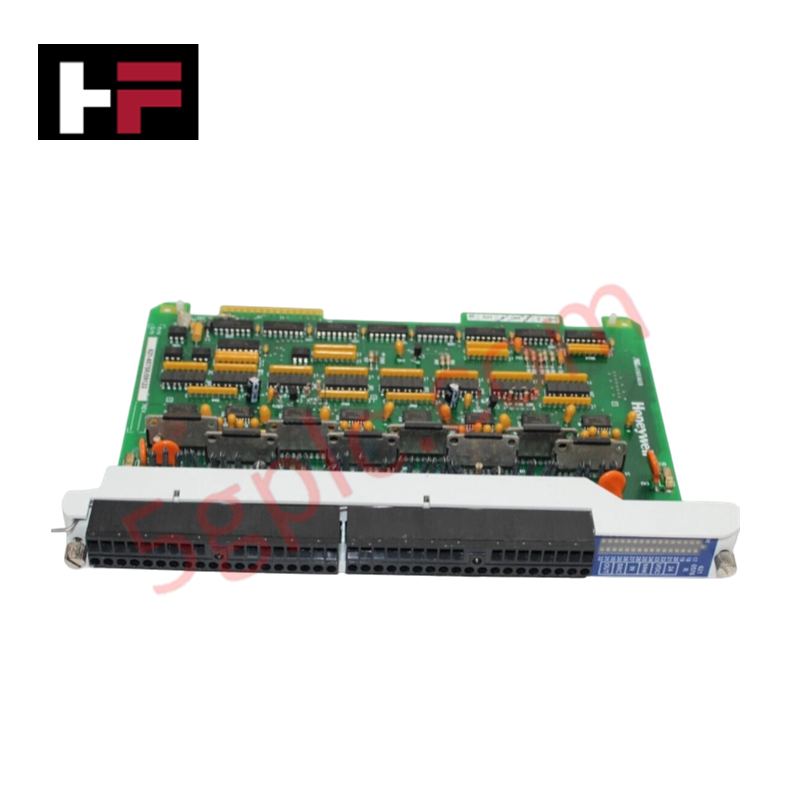
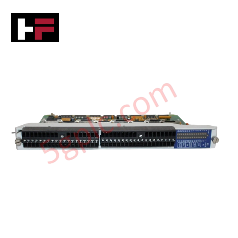
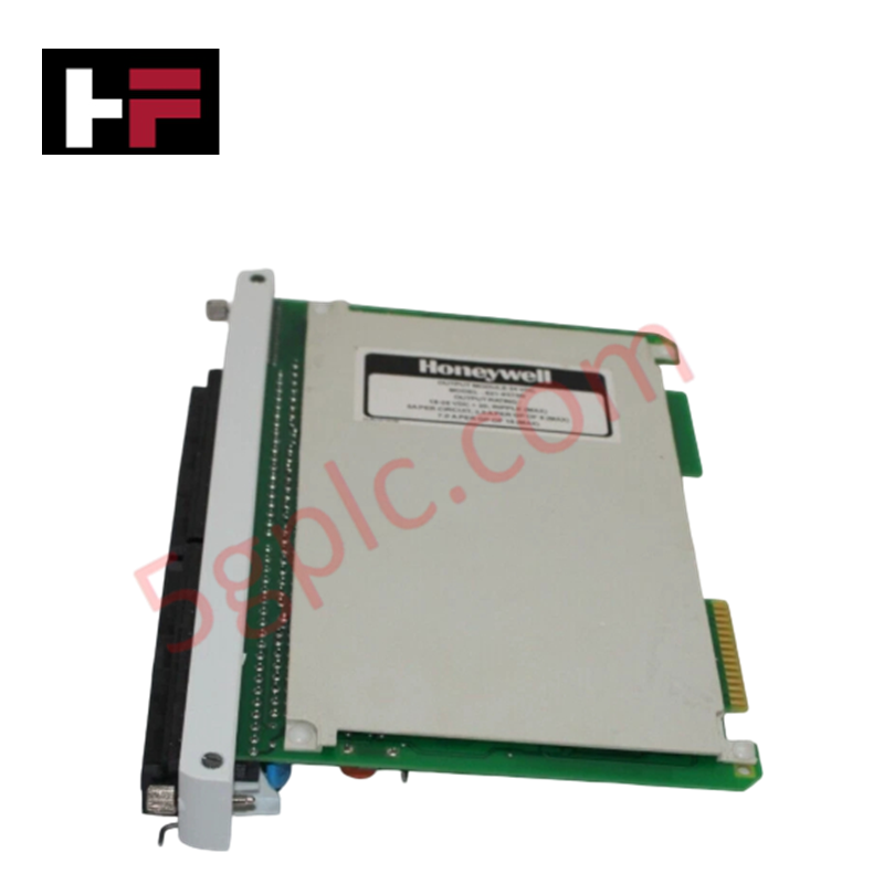
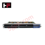
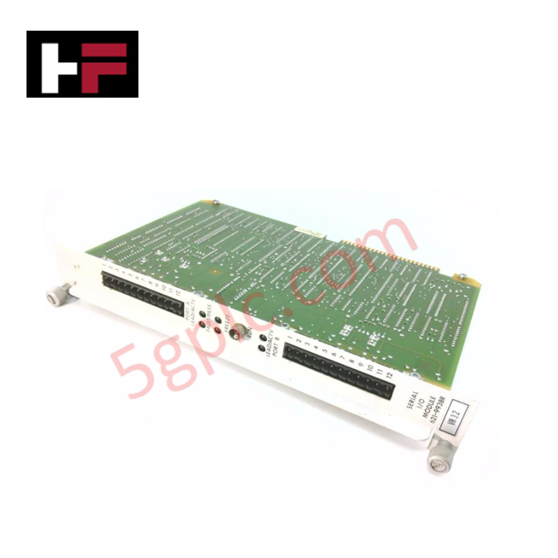
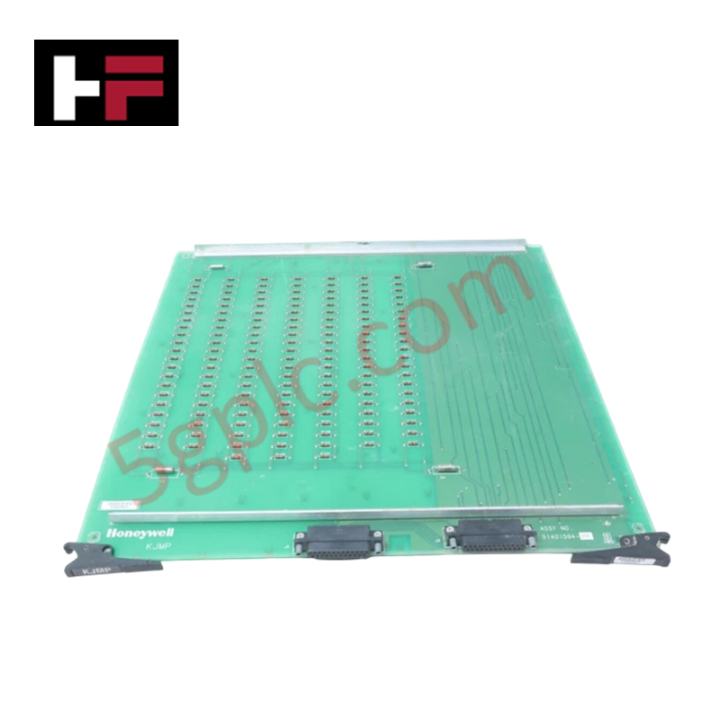
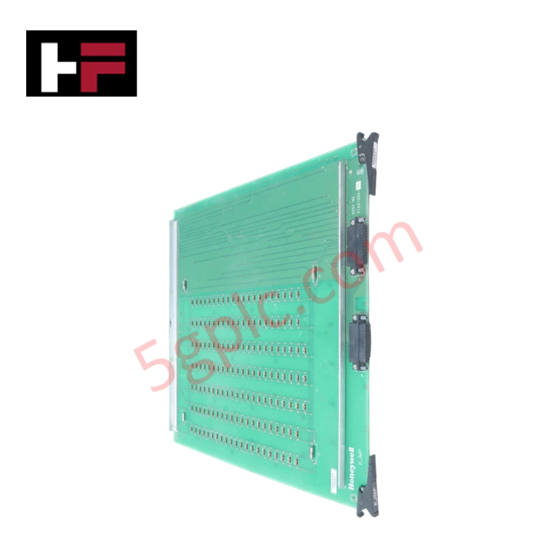
The Honeywell 621-6575R, also cataloged as the 621-6575R Digital Output Module, operates as a dedicated hardware component for 24 VDC discrete signal actuation within Honeywell IPC 620 PLC system racks. Front-panel status LEDs provide immediate visual diagnostic confirmation of per-channel output switching states. The module interface routes internal logic commands across the backplane bus to control field-side loads including solenoids, relays, and pilot indicator circuits.
Hardware Specifications
| Parameter | Specification |
|---|---|
| Model | 621-6575R |
| Brand | Honeywell |
| Origin | USA |
| Weight | 1.54 lbs (0.70 kg) |
| Dimensions | 210 mm x 125 mm x 35 mm |
| Operating Temp | 0 to 60 deg C |
| Power Consumption | 3.8 W |
| Module Type | Digital Output Module |
| Operating Voltage | 24 VDC |
| Diagnostics | Per-Point LED Status Indicators |
Channel-to-Channel Isolation
The 621-6575R module features channel-to-channel isolation architecture to eliminate ground potential loops and suppress cross-talk across adjacent switching paths. Electrical isolation barriers separate internal backplane logic from 24 VDC field output loops, protecting backplane communication buses against field-side inductive voltage spikes, switching noise, and transient surge currents during continuous industrial operation.
Frequently Asked Questions
Q: Can the 621-6575R digital output module be hot-swapped while the IPC 620 rack power is active?
A: No. Module replacement requires turning off the rack power supply to prevent backplane bus communication errors or physical damage to connector pin interfaces.
Q: How do the front-panel status LEDs indicate output switching activity?
A: Each individual LED illuminates when the corresponding logic gate closes and 24 VDC signal power is actively sourced to the field load terminal.
Q: What isolation precautions are necessary when wiring 24 VDC output loads?
A: Field power supply commons must be isolated from chassis ground to maintain channel isolation barriers and prevent external transient currents from entering the controller backplane.
Field Installation Guidelines
- De-energize main chassis power and disconnect field power supply feeds before inserting the module into the IPC 620 rack.
- Align the printed circuit card with the upper and lower slot guides of the chassis and slide the assembly until fully seated in the backplane connector.
- Verify correct 24 VDC supply polarity at the field wiring terminal block prior to applying power.
- Separate 24 VDC discrete output wiring from high-voltage AC cables and sensitive analog signal lines to reduce electromagnetic interference.
- Torquing terminal block screws to manufacturer specification ensures firm contact and prevents terminal heating under continuous current load.
Additional Information
- 100% Genuine Parts: All products are original and authentic, ensuring reliable industrial performance.
- 30-Day Refund Guarantee: Return any in-stock item within 30 days in original, unopened packaging for a full refund (excluding shipping and fees).
- 12-Month Warranty: Covers defects in materials or workmanship; excludes misuse, normal wear, or unauthorized modifications.
- Worldwide Shipping: We ship via USPS, UPS, FedEx, and DHL. Delivery times vary by country and may be subject to customs or import fees.
- Support & Contact: Technical and warranty assistance is available anytime. Contact us here: Contact.
- Purchase Guidance: Check product specifications and compatibility carefully before ordering to ensure proper application.
Tech & Buying Guide

DCS Commissioning Steps in Industrial Automation Projects
Commissioning a Distributed Control System (DCS) represents a crucial milestone when deploying modern process automation infrastructure. Field engineers must execute systematic verification steps to transition complex control hardware from static installation to dynamic plant control. Proper commissioning ensures that controllers, I/O modules, network switches, and HMI software operate in strict compliance with engineering design specifications before introducing live process fluids.

PLC and DCS Control System Spares Strategy: Engineering Guidelines
Modern factory automation relies on high-speed fiber optic backbones to link distributed control systems across noise-intensive industrial environments. Unlike copper wiring, optical fibers transmit data via light pulses, making them completely immune to electromagnetic interference (EMI). Field engineers must master optical cable joining and fusion splicing techniques to guarantee low-loss data transmission across critical Programmable Logic Controller (PLC) and Distributed Control System (DCS) nodes.

PLC and DCS Control System Spares Strategy: Engineering Guidelines
Industrial automation lifecycle management requires robust spare parts planning for Programmable Logic Controller (PLC) and Distributed Control System (DCS) platforms. Plant engineers must correctly categorize spare components during front-end engineering design to maintain high system availability. Miscalculating spare requirements can lead to prolonged unscheduled downtime, project budget overruns, or delayed site commissioning.