


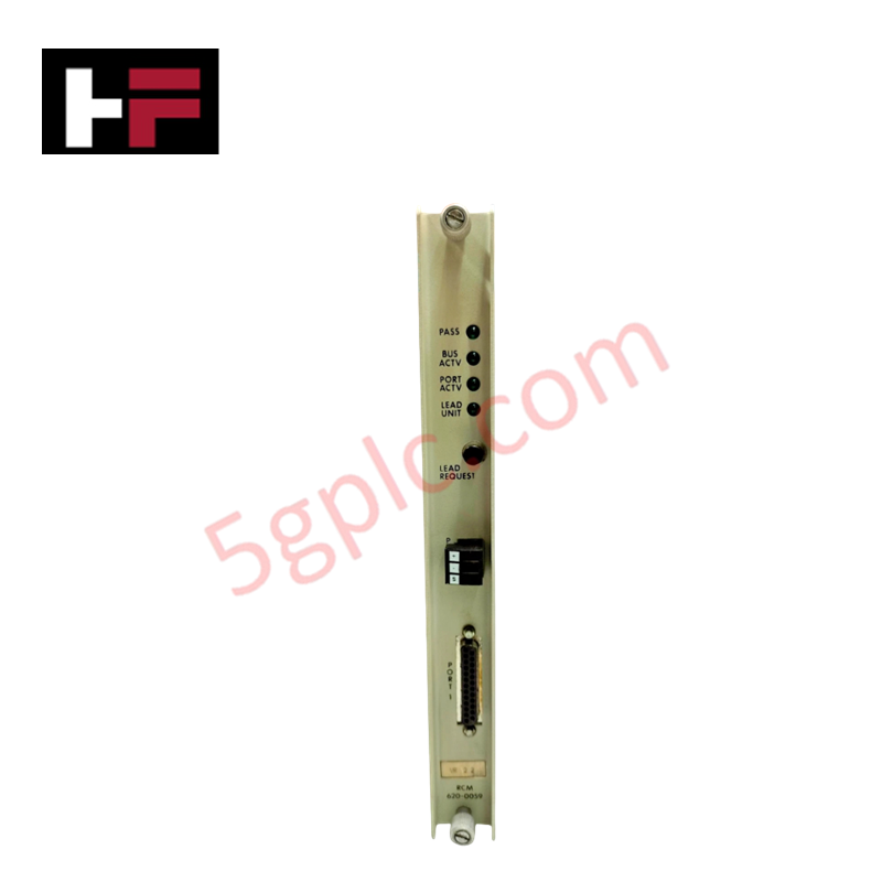


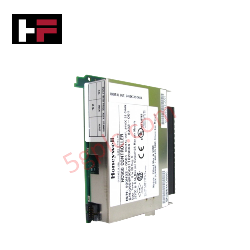
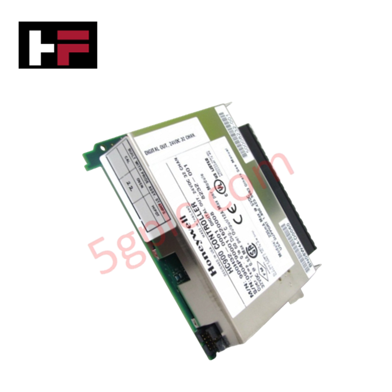
Product Details
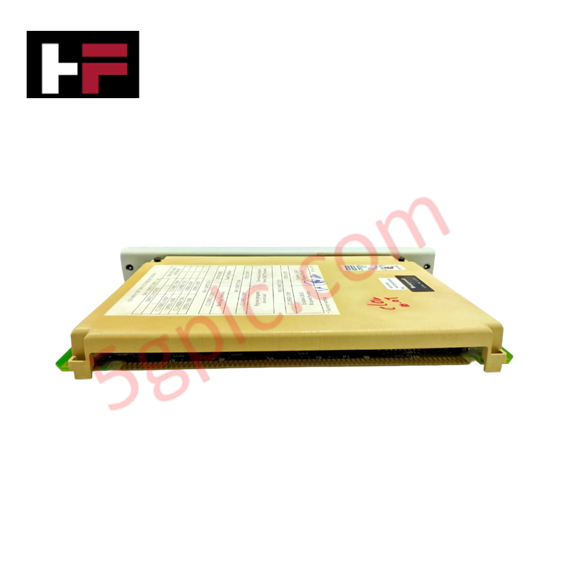
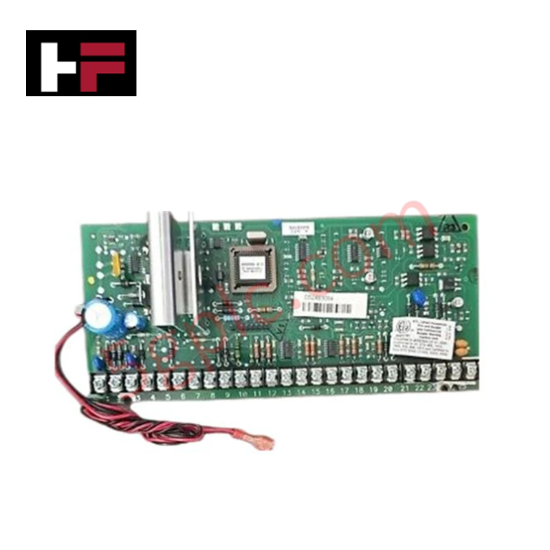
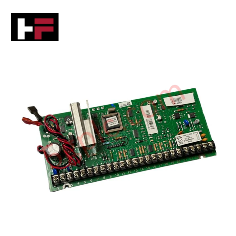
Configured for high-availability control in IPC 620 systems, the Honeywell 620-0059 (620-0059 Redundancy Control Module) provides direct physical execution of primary-to-secondary controller synchronization. This hardware component manages the health monitoring and state-switching logic required to maintain seamless operational continuity, ensuring that the redundant processor set adheres to strict fail-safe state execution protocols during fault events.
Hardware Specifications
| Parameter | Specification |
|---|---|
| Model | 620-0059 |
| Brand | Honeywell |
| Origin | USA |
| Weight | 0.45 kg (1.00 lbs) |
| Dimensions | Not specified |
| Operating Temp | Standard industrial ambient range |
| Power Consumption | 24 VDC |
| Core Performance | Controller state synchronization |
Fail-Safe State Execution and Redundancy Management
The 620-0059 module serves as the primary arbitration unit within the IPC 620 redundancy architecture. It monitors the operational status of the primary CPU and coordinates the transition to the standby controller upon detection of a heartbeat loss or hardware diagnostic error. To ensure effective redundancy, galvanic isolation is maintained between the control module and the backplane logic, preventing fault propagation from the I/O bus to the controller synchronization circuit. In the event of a fault, the module enforces fail-safe state execution, driving critical process outputs to a predetermined safe position to maintain system integrity during the transition interval.
Frequently Asked Questions
Q: Does the 620-0059 support hot-swap replacement?
A: No. The IPC 620 backplane architecture does not support hot-swapping for redundancy modules. Power must be removed from the rack before insertion or extraction of this module.
Q: How is the synchronization heartbeat between controllers maintained?
A: The synchronization heartbeat is managed via a dedicated communication link between redundant 620-0059 modules. This link must be shielded and kept free of electromagnetic interference to prevent false failover triggers.
Field Installation Guidelines
- Slot Placement: Install the module in the designated redundancy controller slot as specified in the IPC 620 chassis map. Ensure positive engagement with the backplane connectors.
- Grounding: The module chassis must be connected to the system earth ground. Improper grounding creates ground loops that interfere with the low-voltage synchronization signals.
- Wiring: Use shielded twisted-pair cabling for inter-controller communication. Route these cables away from high-current power conductors to prevent inductive crosstalk from corrupting the synchronization data.
- Switch Verification: Verify that all DIP switch settings on the redundancy module match the requirements of the primary and secondary controller configuration prior to applying 24 VDC power.
Additional Information
- 100% Genuine Parts: All products are original and authentic, ensuring reliable industrial performance.
- 30-Day Refund Guarantee: Return any in-stock item within 30 days in original, unopened packaging for a full refund (excluding shipping and fees).
- 12-Month Warranty: Covers defects in materials or workmanship; excludes misuse, normal wear, or unauthorized modifications.
- Worldwide Shipping: We ship via USPS, UPS, FedEx, and DHL. Delivery times vary by country and may be subject to customs or import fees.
- Support & Contact: Technical and warranty assistance is available anytime. Contact us here: Contact.
- Purchase Guidance: Check product specifications and compatibility carefully before ordering to ensure proper application.


Tech & Buying Guide

Redundant Automation Systems: Ensuring Continuous Uptime in Critical Control Infrastructure
System reliability directly determines operational profitability across high stakes process industries. Modern industrial automation platforms must eliminate single points of failure to prevent catastrophic shutdowns. Deploying fault tolerant architecture safeguards complex facilities against unexpected hardware glitches, network disruptions, and maintenance outages.

Understanding Types of Noise in Electronic Circuits and Control Systems
Signal integrity directly determines measurement accuracy and loop stability across industrial automation environments. Electronic noise introduces unwanted stochastic interference into analog loops, sensor feedback lines, and digital fieldbus networks. Understanding how intrinsic electronic noise and external electromagnetic interference manifest allows control engineers to optimize signal conditioning and shield sensitive instrumentation effectively.

Why 24V DC Power Supplies Standardize Modern Industrial Automation
Industrial control cabinets worldwide rely on 24V DC as the universal power standard for field instrumentation, sensors, and controllers. Walk into any manufacturing plant, and you will find PLCs, human-machine interfaces (HMIs), and smart actuators running on extra-low voltage DC. Standardizing on 24V DC enhances operational safety, lowers cabinet footprint, and maintains steady control performance across factory networks.