










Product Details
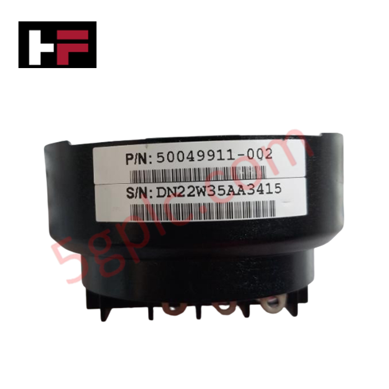
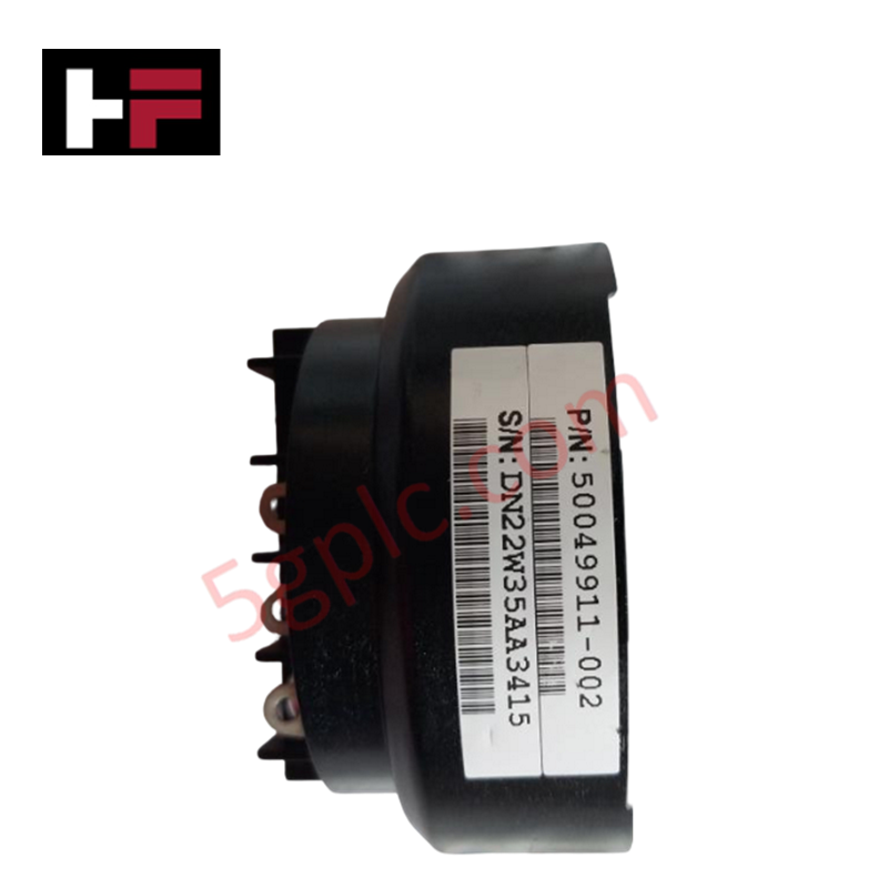
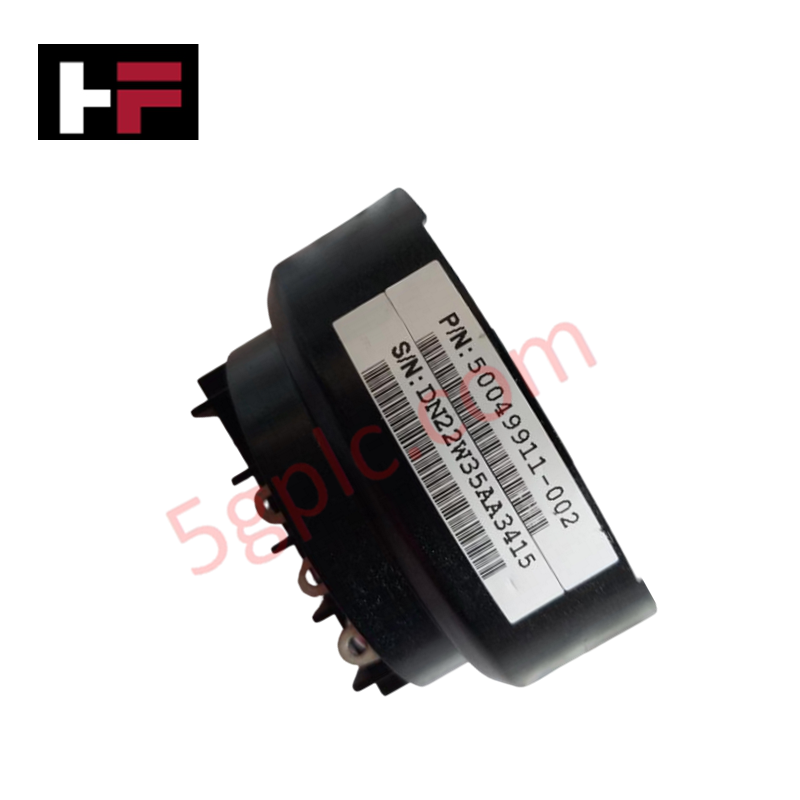
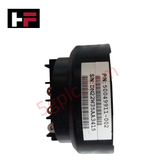
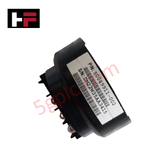
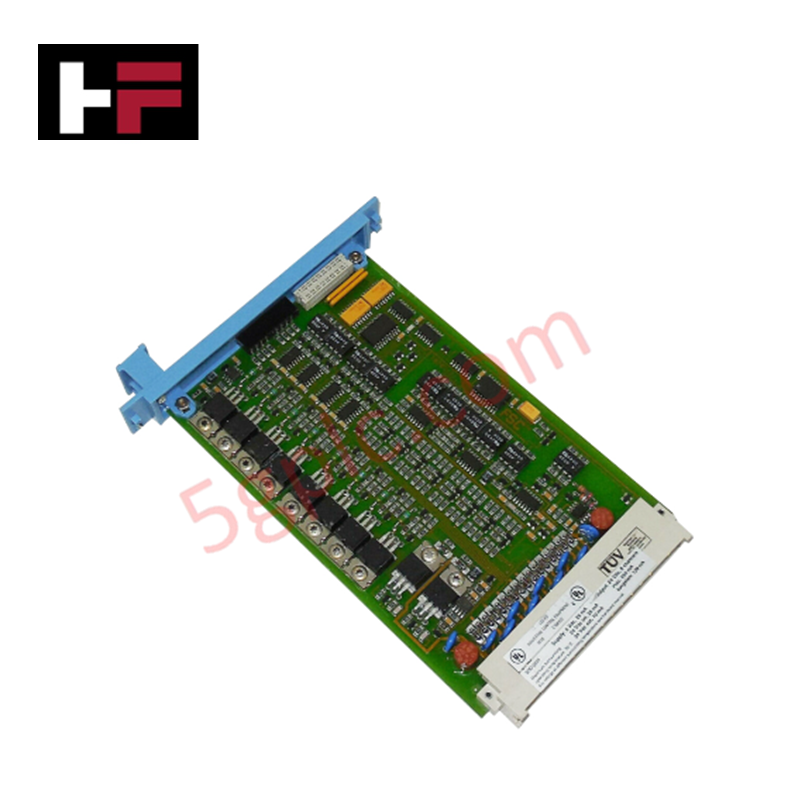
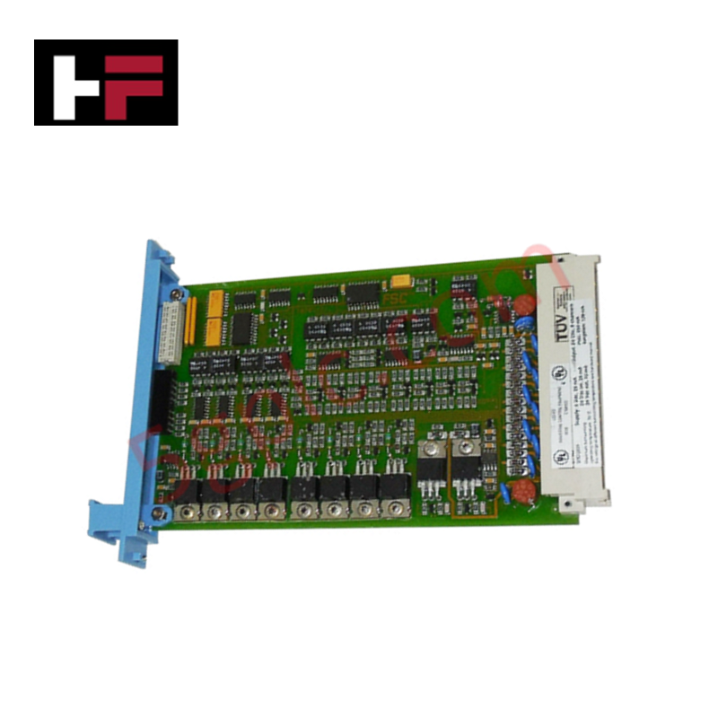
The Honeywell 50049911-002, also cataloged as the 50049911-002 Display Module, operates as a dedicated hardware component for direct visual status monitoring and operator feedback within Honeywell DCS rack platforms. Physical interface circuitry translates internal system bus data into real-time alphanumeric and graphical output. This panel-mounted assembly connects directly to process controller racks, providing direct local diagnostics and system status indications without external host processor overhead.
Hardware Specifications
| Parameter | Specification |
|---|---|
| Model | 50049911-002 |
| Brand | Honeywell |
| Origin | USA |
| Weight | 0.95 kg |
| Dimensions | 180 mm x 110 mm x 45 mm |
| Operating Temp | 0 to 60 deg C |
| Power Consumption | 5.2 W |
| Display Type | Industrial Panel Display Module |
| Interface Bus | Internal Controller Rack Bus |
Channel-to-Channel Isolation
The 50049911-002 incorporates robust channel-to-channel isolation across its power distribution and bus signal interfaces to prevent ground potential loops between the display bezel and internal backplane logic. Galvanic separation shields the display drive electronics against high-voltage field-side surges, suppressing common-mode noise and electrical interference across the controller rack sub-bus.
Frequently Asked Questions
Q: Can the 50049911-002 display module be replaced while the host system rack is powered?
A: No. System rack power must be completely turned off prior to module removal or insertion to prevent backplane bus transients and potential communication disruptions.
Q: How is power provided to the display drive electronics on this module?
A: Regulated DC operating power is drawn directly from the internal controller backplane power rails via the rear interface connector.
Q: What mounting precautions must be observed for the front display panel?
A: Ensure the panel gasket is properly seated against the enclosure cutout to maintain environmental sealing and chassis ground continuity.
Field Installation Guidelines
- Shut down all rack and node power supplies before attempting installation or removal of the module assembly.
- Wear an ESD grounding wrist strap when handling the unit to protect integrated display drivers from static discharge.
- Slide the display module into its designated panel slot along the guide rails until the backplane edge connector fully seats.
- Tighten all panel retention screws evenly to hand-tight torque to maintain structural stability under vibration.
- Verify low-impedance ground bonding between the display bezel housing and the main cabinet enclosure frame.
Additional Information
- 100% Genuine Parts: All products are original and authentic, ensuring reliable industrial performance.
- 30-Day Refund Guarantee: Return any in-stock item within 30 days in original, unopened packaging for a full refund (excluding shipping and fees).
- 12-Month Warranty: Covers defects in materials or workmanship; excludes misuse, normal wear, or unauthorized modifications.
- Worldwide Shipping: We ship via USPS, UPS, FedEx, and DHL. Delivery times vary by country and may be subject to customs or import fees.
- Support & Contact: Technical and warranty assistance is available anytime. Contact us here: Contact.
- Purchase Guidance: Check product specifications and compatibility carefully before ordering to ensure proper application.




Tech & Buying Guide

DCS Commissioning Steps in Industrial Automation Projects
Commissioning a Distributed Control System (DCS) represents a crucial milestone when deploying modern process automation infrastructure. Field engineers must execute systematic verification steps to transition complex control hardware from static installation to dynamic plant control. Proper commissioning ensures that controllers, I/O modules, network switches, and HMI software operate in strict compliance with engineering design specifications before introducing live process fluids.

PLC and DCS Control System Spares Strategy: Engineering Guidelines
Modern factory automation relies on high-speed fiber optic backbones to link distributed control systems across noise-intensive industrial environments. Unlike copper wiring, optical fibers transmit data via light pulses, making them completely immune to electromagnetic interference (EMI). Field engineers must master optical cable joining and fusion splicing techniques to guarantee low-loss data transmission across critical Programmable Logic Controller (PLC) and Distributed Control System (DCS) nodes.

PLC and DCS Control System Spares Strategy: Engineering Guidelines
Industrial automation lifecycle management requires robust spare parts planning for Programmable Logic Controller (PLC) and Distributed Control System (DCS) platforms. Plant engineers must correctly categorize spare components during front-end engineering design to maintain high system availability. Miscalculating spare requirements can lead to prolonged unscheduled downtime, project budget overruns, or delayed site commissioning.