












Product Details
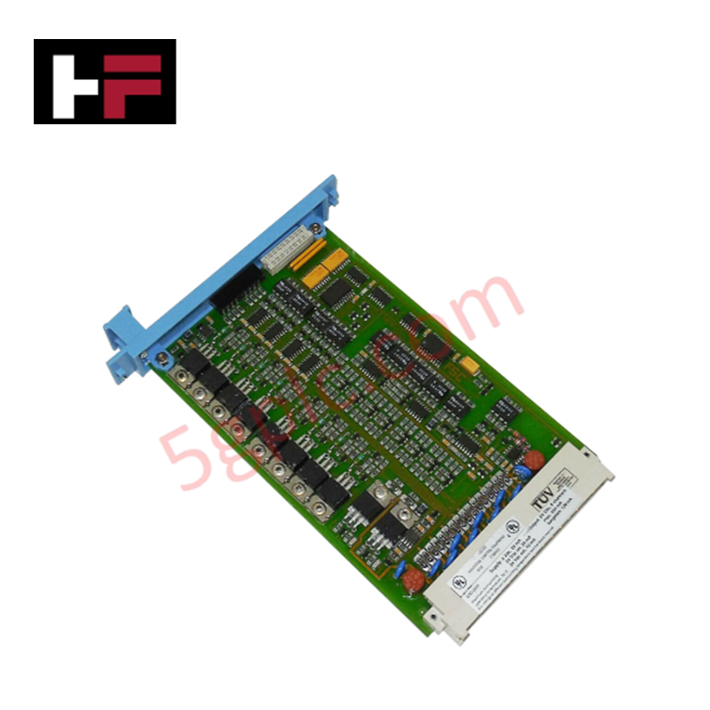
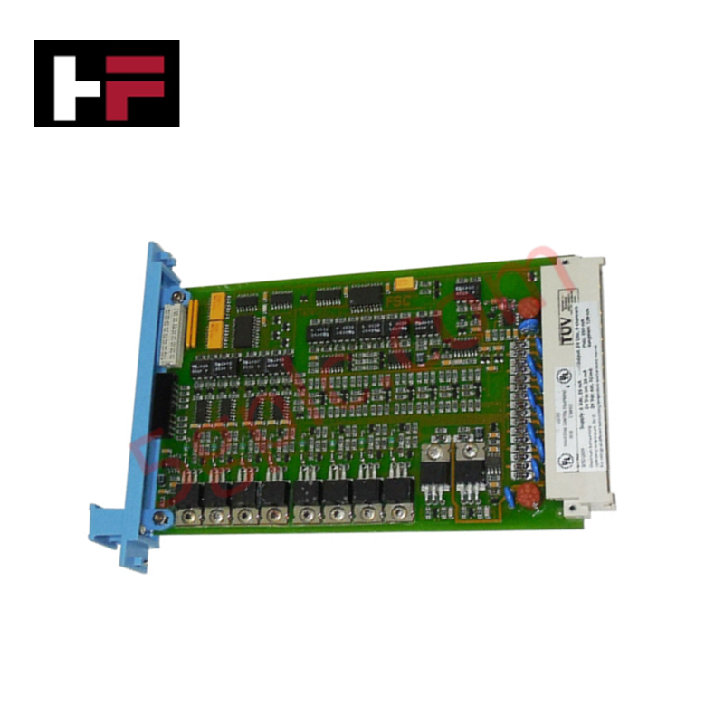
The Honeywell 51202992-100, also cataloged as the 51202992 Digital Output Module, operates as a dedicated hardware component for fail-safe discrete output switching within DCS and Experion PKS platforms. The module provides four independent 24 VDC execution channels to drive field actuators and switching relays directly through the back panel assembly interface.
Hardware Specifications
| Parameter | Specification |
|---|---|
| Model | 51202992-100 |
| Brand | Honeywell |
| Origin | USA |
| Weight | 0.4 kg |
| Dimensions | 12 x 6.3 x 7.8 cm |
| Operating Temp | -20 deg C to +70 deg C |
| Power Consumption | Total Load Capacity: 13 W |
| Input Voltage Range | 85-265 VAC, 47-63 Hz |
| Output Channels | 4 x 24 VDC discrete output channels |
| Channel Output Current | 550 mA per channel |
| Galvanic Isolation | 2500 VDC channel-to-system isolation |
| System Architecture | DCS / Experion PKS Back Panel |
Channel-to-Channel Isolation and CJC Performance
The module incorporates high-density galvanic isolation rated at 2500 VDC to decouple field-side voltage transients from the internal backplane logic. In process control installations using 4-20 mA HART loop protocol instruments alongside high-current discrete outputs, this isolation barrier prevents common-mode noise transfer and eliminates ground loops. Integrated fail-safe architecture forces output channels to drop to a predefined zero-energy state upon loss of communication or power anomalies, protecting downstream instrumentation.
Frequently Asked Questions
Q: What is the maximum continuous current capacity per output channel at elevated ambient temperatures?
A: Each individual output channel supports up to 550 mA at 24 VDC across the entire operating range of -20 deg C to +70 deg C, provided total module power draw does not exceed 13 W.
Q: How does the module execute fail-safe state transitions during backplane bus loss?
A: Upon loss of backplane communication, internal hardware watchdogs trigger immediate channel isolation, dropping all four 24 VDC outputs to 0 VDC within the defined fail-safe execution frame.
Field Installation Guidelines
- Back Panel Mounting: Seat the module firmly onto the back panel slot, verifying that the connector housing engages without pin deflection before tightening retaining screws.
- Shielding & Grounding: Connect all field wiring shield drains to the cabinet's dedicated low-impedance instrumentation ground bar, maintaining separation from protective earth (PE).
- Wiring Separation: Route 24 VDC discrete output field cables in independent raceways away from high-voltage AC distribution power cables, maintaining a minimum physical clearance of 300 mm.
- Thermal Management: Ensure vertical cabinet ventilation channels remain unobstructed to maintain passive air convection across the module chassis.
Additional Information
- 100% Genuine Parts: All products are original and authentic, ensuring reliable industrial performance.
- 30-Day Refund Guarantee: Return any in-stock item within 30 days in original, unopened packaging for a full refund (excluding shipping and fees).
- 12-Month Warranty: Covers defects in materials or workmanship; excludes misuse, normal wear, or unauthorized modifications.
- Worldwide Shipping: We ship via USPS, UPS, FedEx, and DHL. Delivery times vary by country and may be subject to customs or import fees.
- Support & Contact: Technical and warranty assistance is available anytime. Contact us here: Contact.
- Purchase Guidance: Check product specifications and compatibility carefully before ordering to ensure proper application.



Tech & Buying Guide

Understanding PLC Digital Output Types: Relay, Transistor, and Triac Explained
Programmable Logic Controllers (PLCs) form the backbone of modern industrial automation systems. They interface directly with field devices such as solenoid valves, indicator lights, motor starters, and interposing relays. Selecting the correct digital output module ensures high system availability and long hardware service life.

Understanding VFD Mechanical Brake Logic and Control in Industrial Automation
Variable Frequency Drives (VFDs) play a crucial role in modern industrial automation by controlling motor speed, torque, and acceleration. However, high-inertia loads and vertical lifting systems require precise mechanical braking logic to ensure operational safety and prevent equipment damage.

Why Programmable Logic Controllers Drop into Stop Mode: An Expert Analysis
Industrial automation systems rely heavily on Programmable Logic Controllers (PLCs) to maintain uninterrupted production. When a PLC unexpectedly shifts from Run to Stop mode, whole manufacturing lines stall.
As control systems evolve across modern factory automation, understanding the root causes of these interruptions helps engineers minimize costly downtime. This technical guide breaks down why PLCs trip into Stop mode and provides practical strategies to mitigate system faults.