










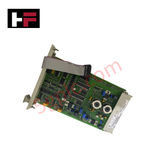
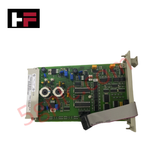
Product Details
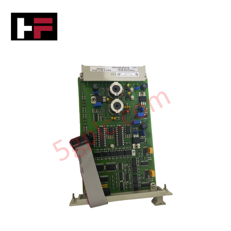
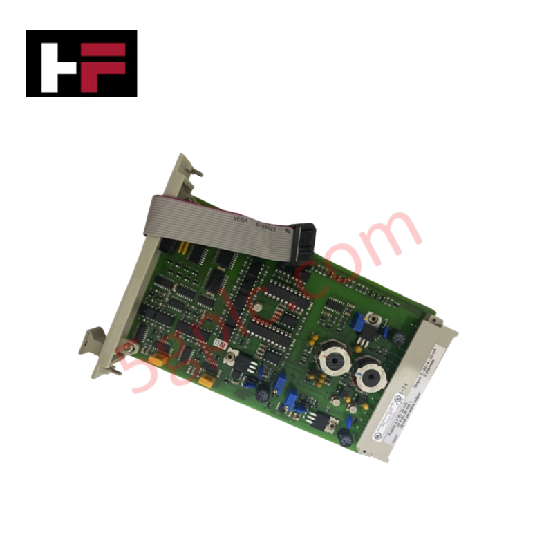
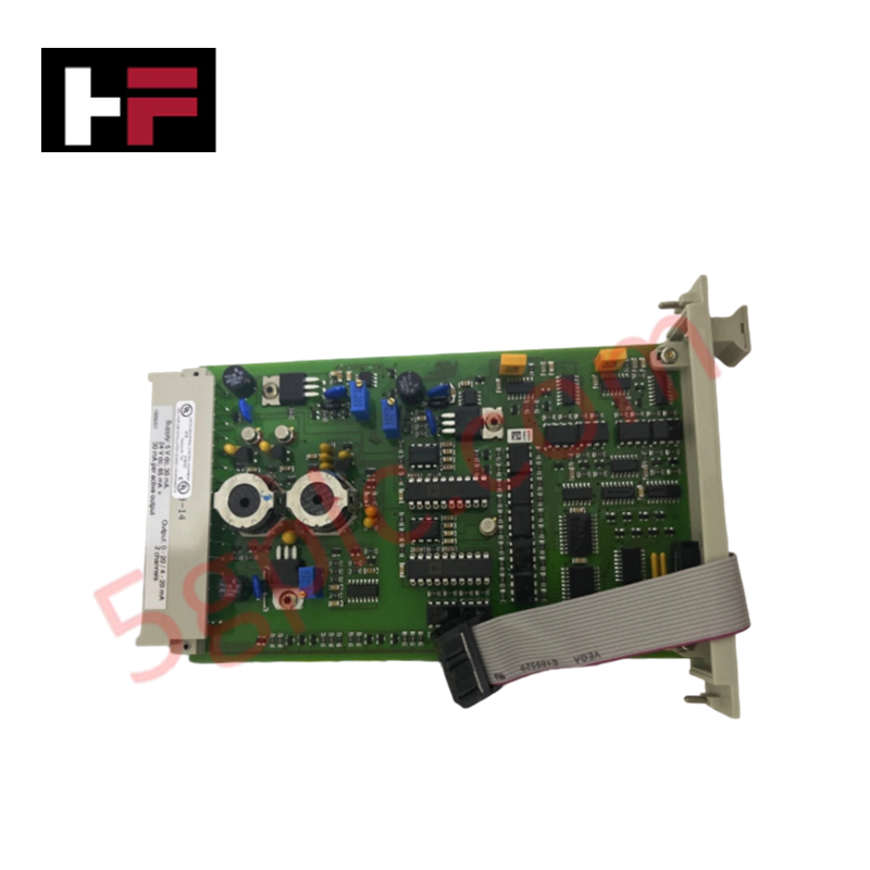
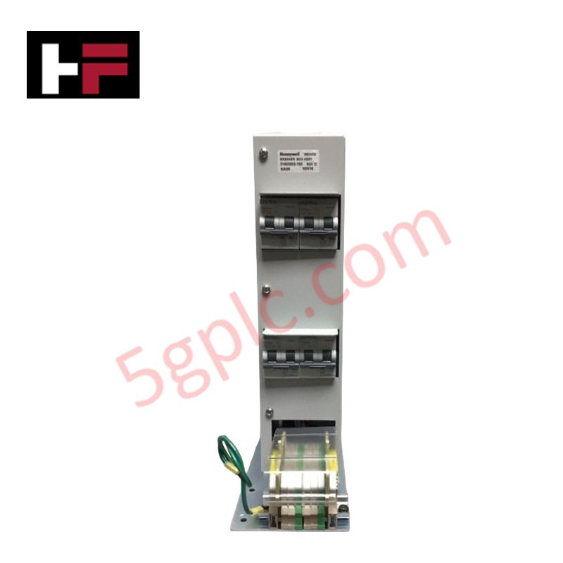
The Honeywell 10205/2/1, also cataloged as the 10205/2/1 Fail-Safe Analog Output Module, operates as a dedicated hardware component for 0(4)-20 mA current loop safety control execution within Fail Safe Controller (FSC) platforms.
Hardware Specifications
| Parameter | Specification |
|---|---|
| Model | 10205/2/1 |
| Brand | Honeywell |
| Origin | USA |
| Weight | 7.00 kg shipping weight |
| Dimensions | 325 x 150 x 150 mm (4 HP, 3U chassis space) |
| Operating Temp | 0 deg C to +60 deg C |
| Power Consumption | 5 VDC at 30 mA, 24 VDC at 65 mA (+ 30 mA per active output) |
| Output Channels | 2 active or passive channels (12-bit D/A conversion) |
| Current Output Range | 0-20 mA / 4-20 mA (Off current < 0.05 mA) |
| Active Loop Resistance | 1000 ohm maximum (30 VDC maximum output voltage) |
| Passive External Voltage | 40 VDC maximum (minimum voltage drop = 7.5 V) |
| Watchdog Input Current | 0.5 mA |
4-20 mA HART Loop Protocol and Channel-to-Channel Isolation
The module provides galvanic isolation between internal power rails and output current channels, with 0V 1 and 0V 2 internally interconnected to stabilize signal reference levels. This isolation architecture prevents ground loop interference, common-mode potential shifts, and external noise transients on active or passive field loops from coupling into adjacent analog processing channels or corrupting 4-20 mA HART loop protocol signals on connected process lines.
Frequently Asked Questions
Q: How is hardware calibration performed on the 10205/2/1 analog output channels?
A: Channel zero and span calibration is executed using potentiometers P2 and P3 on the module, monitored via a multimeter connected through an extender module and flat cable assembly.
Q: What key coding arrangement prevents incorrect module insertion into the rack slot?
A: Physical key coding utilizes holes at locations A9 and C5 on the module, matching large key pins at locations A9 and C5 on the rack backplane.
Q: Can the 10205/2/1 output channels drive passive loops powered by an external source?
A: Yes, each channel can operate in passive mode powered by an external supply up to 40 VDC, maintaining a minimum internal voltage drop of 7.5 V.
Field Installation Guidelines
- Verify rack key coding alignment (pins A9 and C5) before inserting the module into the designated 4 HP width rack slot.
- De-energize the cabinet rack backplane or ensure the proper safety system bypass procedures are engaged prior to extraction or insertion.
- Secure field cabling connections to output terminals, ensuring proper shielding termination to prevent electromagnetic interference on 0(4)-20 mA lines.
- Ensure minimum voltage drop requirements (= 7.5 V) are maintained across the terminals when interfacing external power supplies in passive loop mode.
Additional Information
- 100% Genuine Parts: All products are original and authentic, ensuring reliable industrial performance.
- 30-Day Refund Guarantee: Return any in-stock item within 30 days in original, unopened packaging for a full refund (excluding shipping and fees).
- 12-Month Warranty: Covers defects in materials or workmanship; excludes misuse, normal wear, or unauthorized modifications.
- Worldwide Shipping: We ship via USPS, UPS, FedEx, and DHL. Delivery times vary by country and may be subject to customs or import fees.
- Support & Contact: Technical and warranty assistance is available anytime. Contact us here: Contact.
- Purchase Guidance: Check product specifications and compatibility carefully before ordering to ensure proper application.
Tech & Buying Guide

Industrial Fiber Optic Cables: Principles, Connectors, and Fusion Splicing Techniques
Modern factory automation relies heavily on fiber optic cables for high-speed industrial data transmission. Fiber optic cables transmit light pulses instead of electrical signals, eliminating electromagnetic interference (EMI) risks completely. Each optical strand consists of a high-purity glass core surrounded by a protective cladding layer. The difference in refractive index between core and cladding enables total internal reflection. Protective resin buffers, Kevlar strength members, and rugged outer jackets safeguard delicate glass cores in harsh environments. Consequently, automation engineers prefer fiber backbones for reliable noise-free communication in industrial control systems.

Comprehensive Guide to Instrumentation and Control (I&C) Design Basis
Instrumentation and Control (I&C) Design Basis serves as the foundational technical document for modern plant engineering. Project teams rely on this master specification to govern engineering deliverables across front-end engineering design (FEED) and detailed execution phases. A well-constructed I&C design basis ensures seamless integration among field instrumentation, safety systems, and main control systems. Furthermore, establishing clear technical standards early mitigates execution risks and prevents costly re-engineering during plant commissioning.

The Shift to Flexible IO Modules in Modern Industrial Automation
Traditional control systems rely on dedicated Input Output (IO) cards for industrial automation. Each conventional module processes a single signal type, such as Digital Input (DI), Digital Output (DO), Analog Input (AI), or Analog Output (AO). A standard 16-channel card accepts only one specific channel type across all ports. This inflexible hardware design often creates severe engineering bottlenecks during project execution. Engineers frequently must install entirely new cards to accommodate a single extra sensor. Consequently, late design changes increase control cabinet space requirements and drive up project costs.