


Product Details
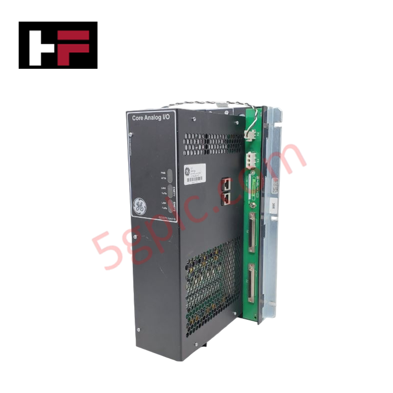
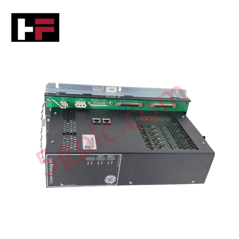
Configured for high-density analog signal processing in Mark VIe distributed control systems, the General Electric IS230PCAAH1B (IS230PCAAH1B I/O Module) provides direct physical/electrical execution of turbine control logic, including LVDT excitation, thermocouple monitoring, and servo coil output regulation.
Hardware Specifications
| Parameter | Specification |
|---|---|
| Model | IS230PCAAH1B |
| Brand | General Electric |
| Origin | U.S.A |
| Weight | Not specified |
| Dimensions | 33.02 cm H x 17.8 cm W |
| Operating Temp | -30 deg C to 65 deg C |
| Power Consumption | Not specified |
| Inputs | 25 total analog inputs |
| Output Range | 4-20 mA current loop and servo driver |
| Supply Voltage | 28 V dc +/- 5% |
Industrial Control and Firmware Integration
The IS230PCAAH1B operates within the Mark VIe I/O network to support complex analog interfaces. The module utilizes deterministic communication links to handle I/O density scaling across simplex, dual, and TMR configurations. Firmware flash compatibility is maintained to synchronize signal processing for LVDT excitation, thermocouple inputs, and servo-loop control. The module architecture is designed for integration with TCAT terminal boards, where signal fan-out is managed across single or multi-module PCAA stacks. Precise signal conversion is maintained for 0-10 V dc inputs and servo driver outputs, ensuring stability within the defined accuracy tolerances across the specified thermal operating range.
Frequently Asked Questions (FAQ)
Q: Can the IS230PCAAH1B be utilized in TMR (Triple Modular Redundant) system configurations?
A: Yes, the PCAA module is engineered for compatibility with simplex, dual, and TMR architectures, allowing for multi-module signal redundancy.
Q: How is the shield grounding managed for this module?
A: Shield grounding and 24 V field power are terminated at the adjacent JGPA board, which provides the necessary common-point ground connection for the signal cabling.
Field Installation Guidelines
- Mechanical Mounting: Mount the module within the designated Mark VIe rack, ensuring proper alignment with the backplane connectors. Verify that the TCAT terminal board is correctly linked for signal fan-out.
- Electrical Termination: Connect the 28 V dc supply to the designated input pins. Ensure the voltage is maintained within the +/- 5% tolerance to prevent erratic LVDT excitation or servo-driver output deviations.
- Signal Cabling: Use shielded cabling for all thermocouple and LVDT inputs. Terminate shields at the JGPA board to prevent electromagnetic interference (EMI) from affecting the analog measurement accuracy.
- Verification: Following installation, perform a diagnostic check via the control software to verify that the PCAA module is communicating correctly with the TCAT/TCAS terminal boards and that all analog channels report values within expected operational ranges.
Additional Information
- 100% Genuine Parts: All products are original and authentic, ensuring reliable industrial performance.
- 30-Day Refund Guarantee: Return any in-stock item within 30 days in original, unopened packaging for a full refund (excluding shipping and fees).
- 12-Month Warranty: Covers defects in materials or workmanship; excludes misuse, normal wear, or unauthorized modifications.
- Worldwide Shipping: We ship via USPS, UPS, FedEx, and DHL. Delivery times vary by country and may be subject to customs or import fees.
- Support & Contact: Technical and warranty assistance is available anytime. Contact us here: Contact.
- Purchase Guidance: Check product specifications and compatibility carefully before ordering to ensure proper application.


Tech & Buying Guide

Mastering the Factory Acceptance Test (FAT) for PLC Control Panels: An Expert Guide
The Factory Acceptance Test (FAT) is a vital milestone in industrial automation that ensures custom PLC panels meet exact design specifications before dispatch. This guide outlines the step-by-step FAT procedure and key industry best practices to prevent costly site delays and ensure long-term operational success.

Redundant Automation Systems: Ensuring Continuous Uptime in Critical Control Infrastructure
System reliability directly determines operational profitability across high stakes process industries. Modern industrial automation platforms must eliminate single points of failure to prevent catastrophic shutdowns. Deploying fault tolerant architecture safeguards complex facilities against unexpected hardware glitches, network disruptions, and maintenance outages.

Understanding Types of Noise in Electronic Circuits and Control Systems
Signal integrity directly determines measurement accuracy and loop stability across industrial automation environments. Electronic noise introduces unwanted stochastic interference into analog loops, sensor feedback lines, and digital fieldbus networks. Understanding how intrinsic electronic noise and external electromagnetic interference manifest allows control engineers to optimize signal conditioning and shield sensitive instrumentation effectively.