


Product Details
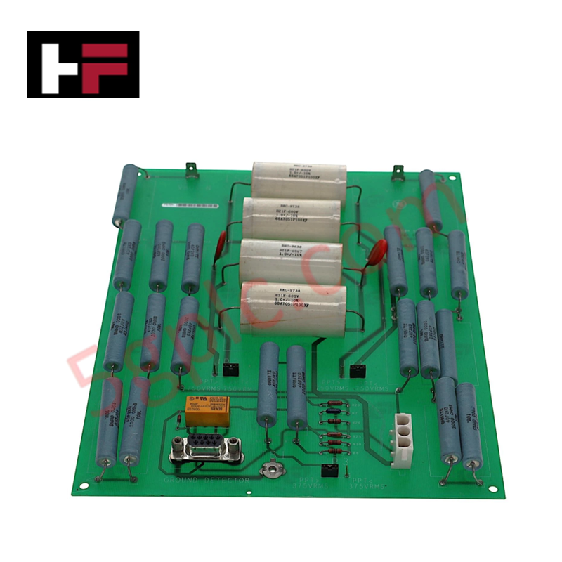
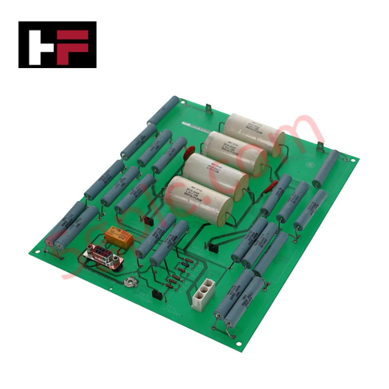
Configured for high-voltage signal attenuation and ground detection interfacing in EX2100 excitation systems, the General Electric IS200EXAMG1AAB (IS200EXAMG1AAB Exciter Attenuation Module) provides direct physical/electrical execution of field bus voltage reduction and signal feedback conditioning.
Hardware Specifications
| Parameter | Specification |
|---|---|
| Model | IS200EXAMG1AAB |
| Brand | General Electric |
| Origin | United States (USA) |
| Operating Temp | 0 deg C to 40 deg C |
| Channels | 13 |
| AC Input Frequency | 480 Hz (max) |
| Field Voltage Range | 125 V dc to 1000 V dc |
| PPT Voltage Range | 120 V ac to 1300 V ac rms |
Excitation Control and Feedback Response
The IS200EXAMG1AAB module is engineered to regulate field current and voltage feedback by attenuating high-voltage bridge signals to levels compatible with the Exciter Ground Detector Module (EGDM). The module supports deterministic network connectivity via the Exciter Power Backplane (EPBP), utilizing a 9-pin interface to ensure low-latency feedback transmission. Its internal architecture is compatible with both simplex and triple modular redundant (TMR) control sections, requiring only a single EXAM unit per system regardless of redundancy configuration. The module’s attenuation circuitry is field-selectable via jumper settings (JP1 and JP2) to accommodate specific power potential transformer (PPT) line-to-line voltage ranges, ensuring stable signal fidelity during transient excitation events.
Frequently Asked Questions (FAQ)
Q: How is the EXAM module linked to the Exciter Ground Detector Module (EGDM)?
A: Both the EXAM and EGDM units interface through the Exciter Power Backplane (EPBP). The EXAM connects via a 9-pin cable, while the EGDM units utilize the 96-pin P2 connector on the same backplane.
Q: What are the criteria for selecting jumper settings JP1 and JP2?
A: Jumper settings must be configured based on the PPT line-to-line voltage. Use specific configurations for voltages below 750 V rms and separate settings for voltages exceeding 750 V rms to ensure proper attenuation characteristics.
Field Installation Guidelines
- Cabinet Placement: The module is designed for installation within the High Voltage Interface (HVI) section of the auxiliary cabinet. Ensure adequate clearance for the 9-pin cable routing to avoid signal crosstalk.
- Jumper Verification: Before applying power to the bridge, verify the JP1 and JP2 jumper positions match the system-specific PPT input voltage requirements. Incorrect settings may lead to signal saturation or damage to downstream EGDM components.
- Grounding and Shielding: To maintain precise feedback monitoring, ensure the module chassis is firmly bonded to the cabinet ground. Shielded cabling should be used for all inputs derived from the field bus to mitigate high-frequency interference.
- Connection Integrity: Ensure the 9-pin cable to the EPBP is fully seated. Given the high-voltage nature of the input signals, verify all terminal connections are tightened to prevent arcing and resistive heating.
Additional Information
- 100% Genuine Parts: All products are original and authentic, ensuring reliable industrial performance.
- 30-Day Refund Guarantee: Return any in-stock item within 30 days in original, unopened packaging for a full refund (excluding shipping and fees).
- 12-Month Warranty: Covers defects in materials or workmanship; excludes misuse, normal wear, or unauthorized modifications.
- Worldwide Shipping: We ship via USPS, UPS, FedEx, and DHL. Delivery times vary by country and may be subject to customs or import fees.
- Support & Contact: Technical and warranty assistance is available anytime. Contact us here: Contact.
- Purchase Guidance: Check product specifications and compatibility carefully before ordering to ensure proper application.


Tech & Buying Guide

Understanding Dry Contacts in PLC Wiring: An Industrial Automation Guide
Mastering contact switching principles is essential for reliable control panels. Field devices and PLCs interface through dry or wet contacts. This technical guide examines the mechanics of dry contacts, explores their wiring architectures, and evaluates their key advantages in industrial automation.

Ultimate Commissioning Checklist for Industrial Automation Systems: An Engineering Guide
Commissioning is the most decisive phase of an industrial automation project, transforming control hardware and software into an operational facility. Thorough testing prevents costly startup delays and builds customer confidence. This guide covers essential checklists, electrical standards, and best practices.

Redundant Automation Systems: Core Architecture, Business Value, and Technical Advantages
Unplanned downtime poses a major financial threat to process manufacturing. To prevent costly interruptions, engineers deploy redundant PLC and DCS architectures that ensure continuous operation when hardware fails. This technical guide explores redundancy principles, critical system nodes, and real-world scenarios.