










Product Details
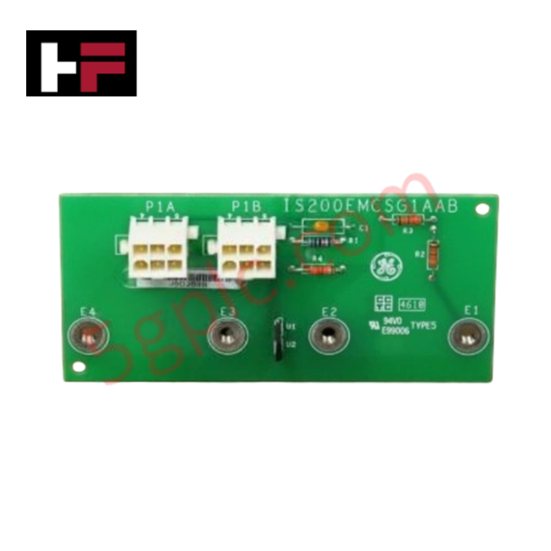
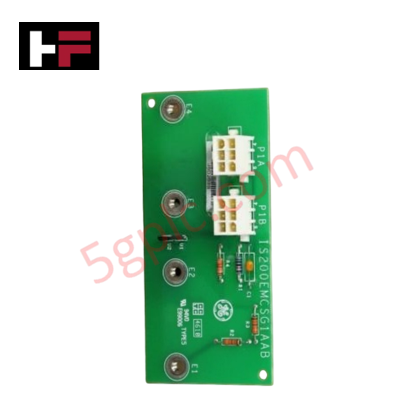
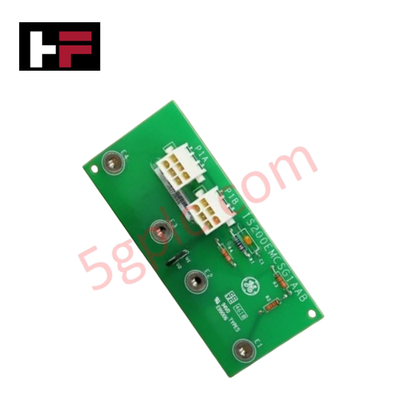
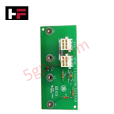
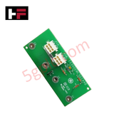
Configured for high-current conduction monitoring in EX2100 innovation series excitation systems, the General Electric IS200EMCSG1A (IS200EMCSG1A Multibridge Conduction Sensor Board) provides direct physical/electrical execution of sensor circuit feedback across a multibridge interface.
Hardware Specifications
| Parameter | Specification |
|---|---|
| Model | IS200EMCSG1A |
| Brand | General Electric |
| Origin | United States of America (USA) |
| Weight | < 1 lb |
| Dimensions | 11.05 cm x 5.08 cm |
| Operating Temp | Not specified |
| Power Consumption | Not specified |
| Conduction Sensors | 4 (E1-E4) |
| Connectors | Two six-plug power inputs |
Industrial Control and Firmware Integration
The IS200EMCSG1A utilizes backplane bus communication velocity to interface with excitation control racks. While the module is hardware-centric with discrete components including metal film resistors and ceramic capacitors, it maintains firmware flash compatibility through host controllers that manage the sensor data inputs. The board facilitates I/O density scaling by supporting four independent conduction sensors (E1-E4) and two auxiliary sensor circuits (U1-U2). Its design allows for deployment in high-current paths, providing localized conduction state detection relayed to the host excitation system.
Frequently Asked Questions (FAQ)
Q: What is the configuration of the auxiliary sensor circuits on the board?
A: The board features two independent sensor circuits labeled U1 and U2, positioned between conduction sensors E2 and E3, which complement the four primary conduction sensors (E1-E4).
Q: How is power provided to the board?
A: Power is supplied through two six-plug connectors located on the board edge opposite the conduction sensors. These connectors provide the necessary bias for the onboard sensor circuits.
Field Installation Guidelines
- Mechanical Placement: Ensure the board is mounted in an environment free from excessive vibration to prevent mechanical strain on the sensor leads and connectors.
- Connection Integrity: Inspect the two six-plug power connectors for terminal oxidation before installation. Ensure that all power supply mating connectors are fully latched to avoid intermittent feedback signals.
- Shielding and Grounding: Given the high-current nature of the conduction paths monitored, route all signal wiring away from primary power conductors to minimize induced noise. Verify that the board mounting hardware provides a clean common reference to the system ground.
- Thermal Management: While the board is designed to support high currents, ensure adequate convection cooling within the exciter cabinet to maintain the operational stability of the metal film resistors and ceramic capacitors.
Additional Information
- 100% Genuine Parts: All products are original and authentic, ensuring reliable industrial performance.
- 30-Day Refund Guarantee: Return any in-stock item within 30 days in original, unopened packaging for a full refund (excluding shipping and fees).
- 12-Month Warranty: Covers defects in materials or workmanship; excludes misuse, normal wear, or unauthorized modifications.
- Worldwide Shipping: We ship via USPS, UPS, FedEx, and DHL. Delivery times vary by country and may be subject to customs or import fees.
- Support & Contact: Technical and warranty assistance is available anytime. Contact us here: Contact.
- Purchase Guidance: Check product specifications and compatibility carefully before ordering to ensure proper application.


Tech & Buying Guide

Spatial Computing in Industrial Automation: Elevating PLC and DCS Operations with AR and VR
Industry 4.0 integrates digital intelligence into field operations, transforming factory automation landscapes worldwide. Spatial technologies—specifically Augmented Reality (AR) and Virtual Reality (VR)—redefine how engineers interact with industrial control systems. By bridging computer-generated CAD models with real-time operational technology (OT) data, immersive displays enable intuitive monitoring, rapid diagnostics, and safer maintenance across complex processing facilities.

Master Acceptance Testing: Understanding FAT and SAT in Industrial Control Systems
Factory Acceptance Testing (FAT) and Site Acceptance Testing (SAT) serve as critical quality assurance gateways in complex industrial control systems. Both procedures verify that programmable logic controllers (PLCs), distributed control systems (DCS), and associated field devices meet strict functional specifications. However, executing these tests effectively requires clear delineation between off-site staging and final field commissioning.

Industrial Networking Essentials: Demystifying Hubs, Switches, and Routers in Control Systems
Industrial automation relies heavily on robust networking infrastructure to connect programmable logic controllers (PLCs), distributed control systems (DCS), and human-machine interfaces (HMIs). Modern factory automation environments generate vast amounts of real-time operational data across deterministic networks. Understanding the structural differences between hubs, switches, and routers ensures optimal traffic segmentation, minimizes latency, and maintains high network availability.