


Product Details
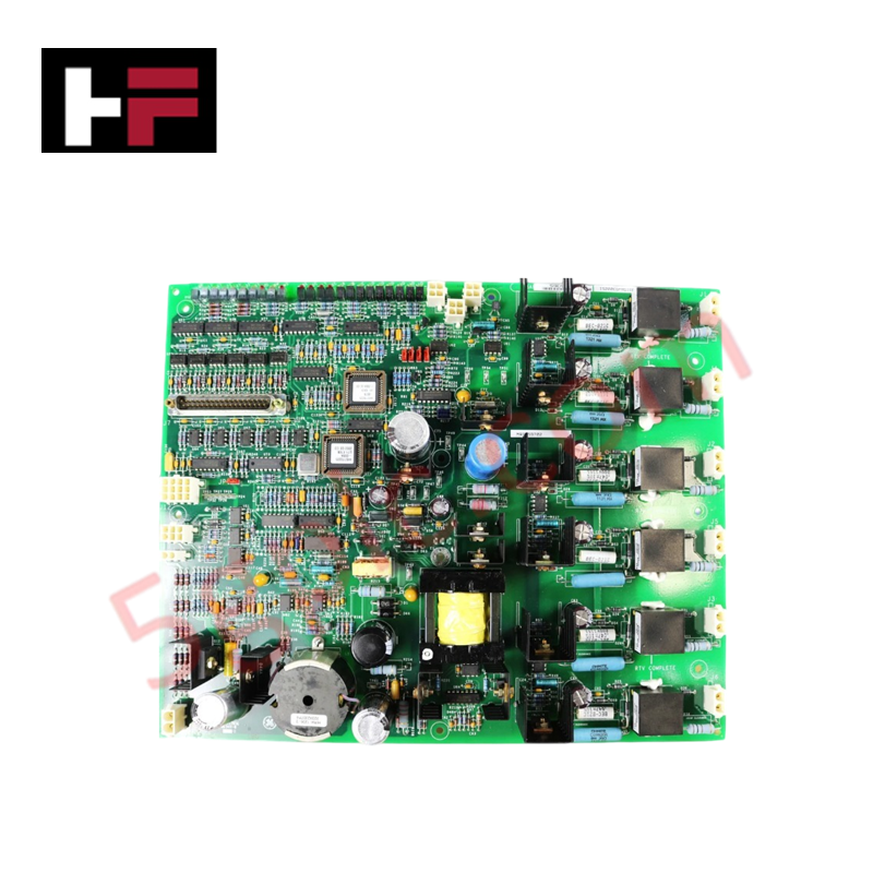
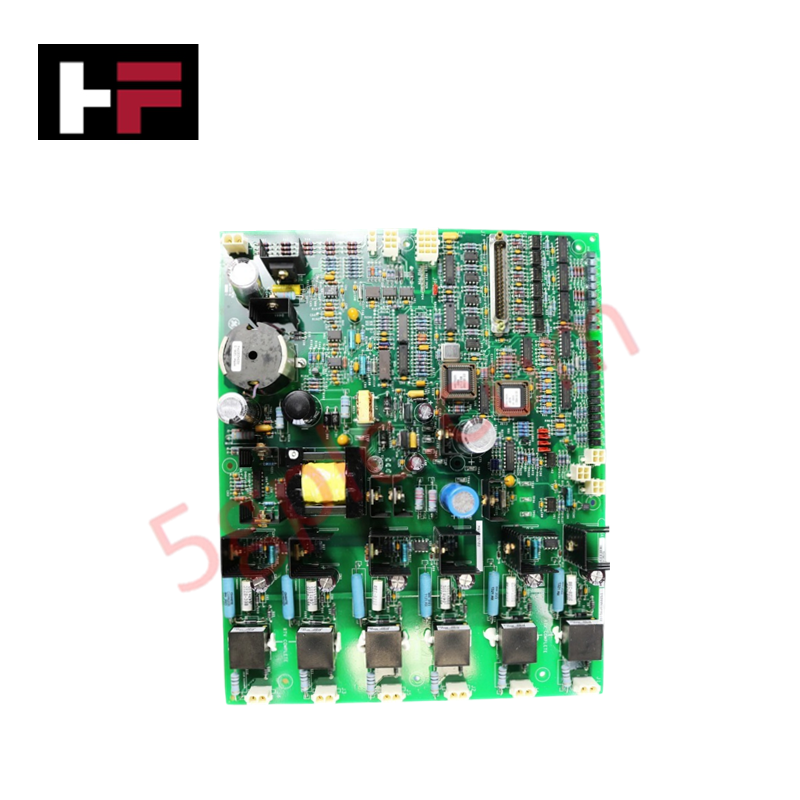
Configured for high-power SCR gating and bridge monitoring in EX2100 Excitation Control systems, the General Electric IS200EGPAG1BEC (IS200EGPAG1BEC Exciter Gate Pulse Amplifier Board) provides direct physical/electrical execution of gate command processing and power bridge regulation.
Hardware Specifications
| Parameter | Specification |
|---|---|
| Model | IS200EGPAG1BEC |
| Brand | General Electric |
| Origin | United States (USA) |
| Dimensions | 168 mm x 150 mm x 55 mm |
| Operating Temp | 40 deg C to 70 deg C |
| Power Consumption | +5 V dc, 6 A |
| Input Channels | 24 |
| Trip Solenoid Rating | 125 V dc |
| Supply Voltage | 28 V dc |
Industrial Control and Firmware Integration
The IS200EGPAG1BEC integrates into the EX2100 architecture to enable precise firing of up to six Silicon Controlled Rectifiers (SCRs). The board utilizes firmware flash compatibility to interface with ESEL gate command signals, ensuring deterministic execution of firing sequences within the power bridge. The module manages complex I/O density scaling to monitor bridge parameters, including thermal profiles, current flow, and cooling fan status, which are transmitted back to the control system for diagnostic analysis. The on-board dc/dc converter maintains stable gate pulse propagation regardless of bridge input voltage fluctuations, ensuring consistent bridge performance.
Frequently Asked Questions (FAQ)
Q: Is the IS200EGPAG1BEC field-replaceable in an active EX2100 bridge?
A: Replacement should only occur when the exciter is in a safe, de-energized state. Ensure all gate signal ribbon cables and power input headers are secured after installation to maintain electrical continuity.
Q: How do the LED indicators on the board facilitate troubleshooting?
A: The onboard LEDs provide real-time status for input gate commands, SCR output firing, and diagnostic conditions such as bridge temperature, cooling fan activity, and fault alarms, allowing for immediate visual verification of bridge health.
Field Installation Guidelines
- Mounting: Secure the board to the designated slots within the EX2100 excitation cabinet. Ensure that the mechanical fasteners are tightened to maintain grounding continuity to the chassis.
- Cabling: Connect the 24 input channels and power supply inputs to the specified header blocks. Use appropriate cable management to prevent strain on the board-mounted connectors.
- Thermal Management: Given the operational range of 40 deg C to 70 deg C, verify that the cabinet cooling fans are operational and that airflow paths across the power bridge components are unobstructed.
- Grounding: Ensure the excitation control common is connected to the ground bus to prevent common-mode noise from affecting the gate pulse timing and amplifier signals.
- Verification: Following installation, perform a bridge diagnostic cycle via the QNX-based operating system to confirm that all SCR firing signals are correctly mapped and that no alarm states are triggered under nominal load.
Additional Information
- 100% Genuine Parts: All products are original and authentic, ensuring reliable industrial performance.
- 30-Day Refund Guarantee: Return any in-stock item within 30 days in original, unopened packaging for a full refund (excluding shipping and fees).
- 12-Month Warranty: Covers defects in materials or workmanship; excludes misuse, normal wear, or unauthorized modifications.
- Worldwide Shipping: We ship via USPS, UPS, FedEx, and DHL. Delivery times vary by country and may be subject to customs or import fees.
- Support & Contact: Technical and warranty assistance is available anytime. Contact us here: Contact.
- Purchase Guidance: Check product specifications and compatibility carefully before ordering to ensure proper application.


Tech & Buying Guide

Understanding Dry Contacts in PLC Wiring: An Industrial Automation Guide
Mastering contact switching principles is essential for reliable control panels. Field devices and PLCs interface through dry or wet contacts. This technical guide examines the mechanics of dry contacts, explores their wiring architectures, and evaluates their key advantages in industrial automation.

Ultimate Commissioning Checklist for Industrial Automation Systems: An Engineering Guide
Commissioning is the most decisive phase of an industrial automation project, transforming control hardware and software into an operational facility. Thorough testing prevents costly startup delays and builds customer confidence. This guide covers essential checklists, electrical standards, and best practices.

Redundant Automation Systems: Core Architecture, Business Value, and Technical Advantages
Unplanned downtime poses a major financial threat to process manufacturing. To prevent costly interruptions, engineers deploy redundant PLC and DCS architectures that ensure continuous operation when hardware fails. This technical guide explores redundancy principles, critical system nodes, and real-world scenarios.