


Product Details
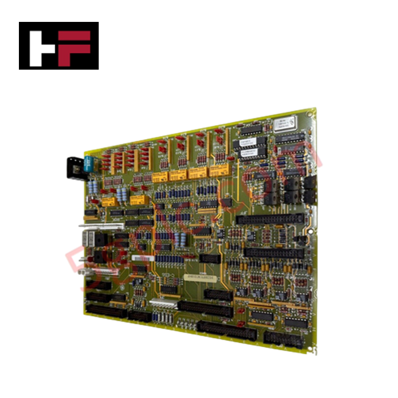
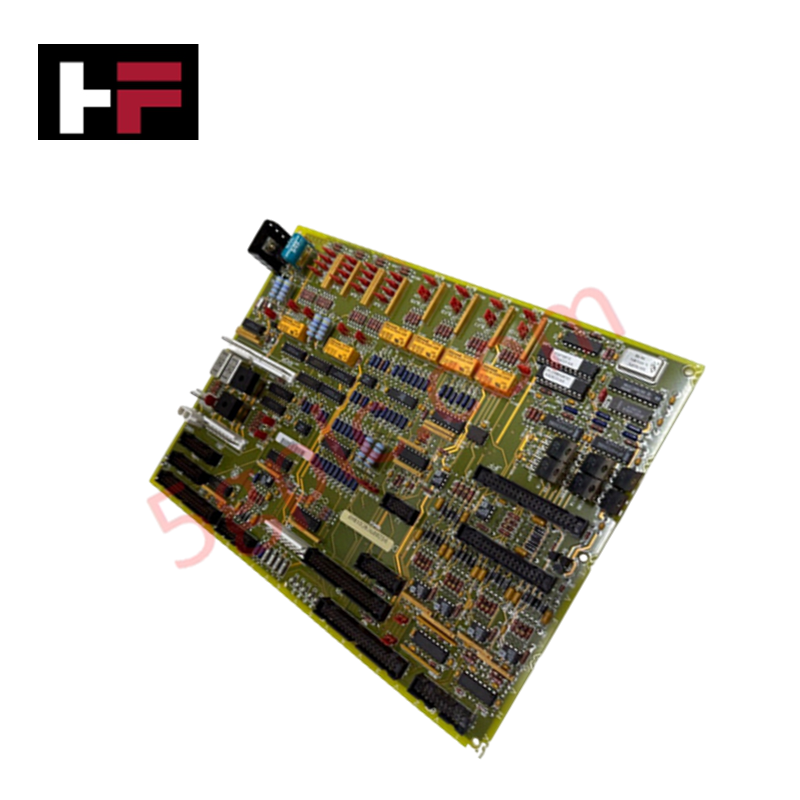
The GE DS200TCQCG1BHF, also cataloged as the DS200TCQCG1BHF Overflow Card, operates as a dedicated hardware component for LVDT and LVDR signal excitation within Mark V Speedtronic control systems.
Hardware Specifications
| Parameter | Specification |
|---|---|
| Model | DS200TCQCG1BHF |
| Brand | General Electric |
| Function | Analog I/O Overflow Card |
Industrial Control & Firmware Compatibility
The DS200TCQCG1BHF board interfaces with control systems to manage analog feedback loops. For successful integration, ensure that backplane bus communication velocity settings are verified within the Mark V configuration environment. The board incorporates 37 jumper switches to facilitate hardware-level configuration, which must be set according to the specific excitation requirements of the connected LVDT/LVDR sensors. Firmware flash compatibility is managed via the host controller interface; ensure that the system firmware revision aligns with the board's I/O density scaling capabilities to maintain deterministic network performance.
Frequently Asked Questions
Q: What is the function of the onboard jumper switches?
A: The 37 jumper switches configure the board's operational parameters, including excitation levels for LVDT and LVDR sensors. These must be set to match the specific physical requirements of the feedback loops before system startup.
Q: Can this board be hot-swapped during active turbine operation?
A: Mark V control system modules are typically not designed for hot-swap operations. The system must be placed in a maintenance state, and power to the specific backplane slot must be isolated before removing or installing the board to prevent electrical transients.
Field Installation Guidelines
- Physical Mounting: Ensure the board is firmly seated in the assigned VME rack slot. Verify that all vertical pin cable connectors are fully engaged to prevent intermittent signal continuity, which can trigger control system alarms.
- Jumper Configuration: Prior to installation, confirm the jumper switch settings match the site-specific technical manual for the target application. Incorrect jumper placement may lead to improper excitation voltage levels, causing sensor signal saturation or drift.
- Component Inspection: Given the density of components (including over 25 resistor networks and 40 integrated circuits), inspect the board for any mechanical damage or debris that may have occurred during handling. Ensure the heat sink is free of dust to maintain proper thermal dissipation profiles.
- Signal Shielding: Use high-quality shielded cables for all I/O connections to the pin headers. Proper grounding of the cable shields at the control cabinet entry point is required to minimize electromagnetic interference that could affect analog measurement accuracy.
Additional Information
- 100% Genuine Parts: All products are original and authentic, ensuring reliable industrial performance.
- 30-Day Refund Guarantee: Return any in-stock item within 30 days in original, unopened packaging for a full refund (excluding shipping and fees).
- 12-Month Warranty: Covers defects in materials or workmanship; excludes misuse, normal wear, or unauthorized modifications.
- Worldwide Shipping: We ship via USPS, UPS, FedEx, and DHL. Delivery times vary by country and may be subject to customs or import fees.
- Support & Contact: Technical and warranty assistance is available anytime. Contact us here: Contact.
- Purchase Guidance: Check product specifications and compatibility carefully before ordering to ensure proper application.


Tech & Buying Guide

Mastering the Factory Acceptance Test (FAT) for PLC Control Panels: An Expert Guide
The Factory Acceptance Test (FAT) is a vital milestone in industrial automation that ensures custom PLC panels meet exact design specifications before dispatch. This guide outlines the step-by-step FAT procedure and key industry best practices to prevent costly site delays and ensure long-term operational success.

Redundant Automation Systems: Ensuring Continuous Uptime in Critical Control Infrastructure
System reliability directly determines operational profitability across high stakes process industries. Modern industrial automation platforms must eliminate single points of failure to prevent catastrophic shutdowns. Deploying fault tolerant architecture safeguards complex facilities against unexpected hardware glitches, network disruptions, and maintenance outages.

Understanding Types of Noise in Electronic Circuits and Control Systems
Signal integrity directly determines measurement accuracy and loop stability across industrial automation environments. Electronic noise introduces unwanted stochastic interference into analog loops, sensor feedback lines, and digital fieldbus networks. Understanding how intrinsic electronic noise and external electromagnetic interference manifest allows control engineers to optimize signal conditioning and shield sensitive instrumentation effectively.