


Product Details
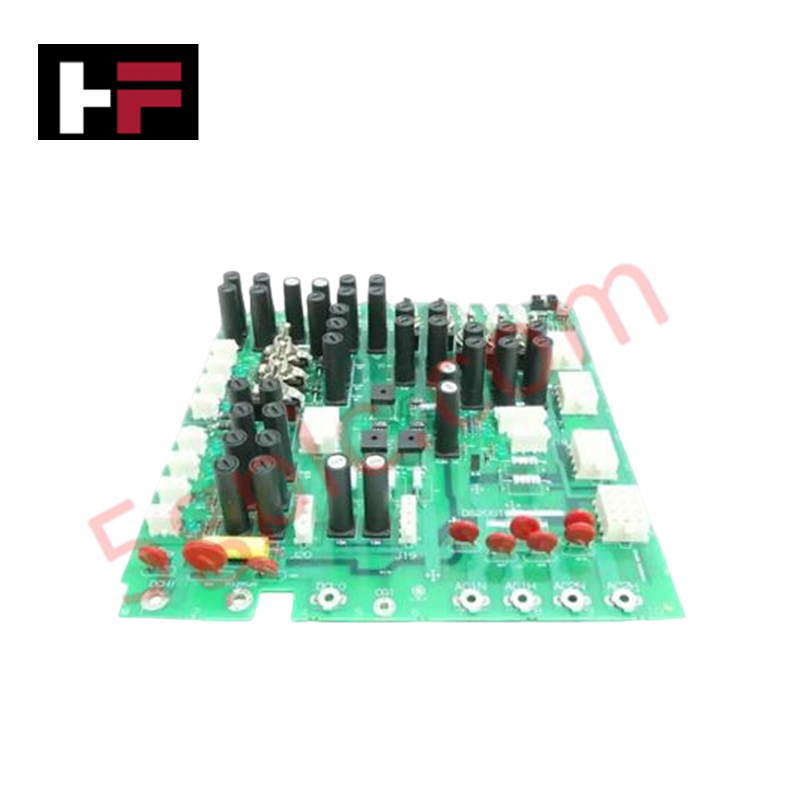
Configured for power signal routing in Mark V systems, the GE DS200TCPDG2BEC (DS200TCPD Power Distribution Board) provides direct physical execution of voltage distribution across drive internal circuitry.
Hardware Specifications
| Parameter | Specification |
|---|---|
| Model | DS200TCPDG2BEC |
| Brand | General Electric |
| Origin | USA |
| Weight | 0.8 kg |
| Dimensions | 14.75 cm x 9.50 cm x 3.50 cm |
| Core Function | Drive power signal distribution |
Industrial Control & Firmware Compatibility
The DS200TCPDG2BEC manages the distribution of regulated DC and AC voltages to auxiliary drive cards. Backplane bus communication velocity is not applicable to this board, as its primary function is the transmission of raw and regulated power rather than data packets. I/O density scaling is handled via high-current traces designed to interface with various control and power boards within the drive rack. Firmware flash compatibility is not required for this component. Proper operation requires consistent voltage levels from the upstream power supply to ensure downstream stability of the connected drive components.
Frequently Asked Questions
Q: Does the DS200TCPDG2BEC require firmware updates?
A: No. This board is a passive power distribution component. It contains no microprocessors or programmable logic and therefore does not support or require firmware updates.
Q: Can this board be replaced while the drive cabinet is powered?
A: No. Disconnect all primary AC and DC power sources from the drive before attempting removal or installation. The board handles power distribution for multiple circuits, and improper handling while energized poses a risk of electrical shock and damage to connected auxiliary modules.
Field Installation Guidelines
- Physical Seating: Ensure the board is aligned with the cabinet power bus and firmly secured using the provided mounting hardware. Verify that all power connectors are fully engaged to prevent resistive heating at the contact points.
- Wiring Verification: Cross-reference the connection points with the cabinet wiring diagram to ensure proper phase and polarity alignment. Incorrect wiring can lead to short circuits or damage to downstream control boards.
- Shielding and Grounding: Maintain cabinet ground integrity. The board must be mounted in a manner that ensures chassis-to-board grounding, minimizing the potential for electromagnetic noise injection into sensitive control signal paths.
- Thermal Management: Ensure that airflow within the drive cabinet is not obstructed by cabling routed near the distribution board. Maintain adequate clearance to allow heat dissipation from current-carrying traces.
Additional Information
- 100% Genuine Parts: All products are original and authentic, ensuring reliable industrial performance.
- 30-Day Refund Guarantee: Return any in-stock item within 30 days in original, unopened packaging for a full refund (excluding shipping and fees).
- 12-Month Warranty: Covers defects in materials or workmanship; excludes misuse, normal wear, or unauthorized modifications.
- Worldwide Shipping: We ship via USPS, UPS, FedEx, and DHL. Delivery times vary by country and may be subject to customs or import fees.
- Support & Contact: Technical and warranty assistance is available anytime. Contact us here: Contact.
- Purchase Guidance: Check product specifications and compatibility carefully before ordering to ensure proper application.


Tech & Buying Guide

Redundant Automation Systems: Ensuring Continuous Uptime in Critical Control Infrastructure
System reliability directly determines operational profitability across high stakes process industries. Modern industrial automation platforms must eliminate single points of failure to prevent catastrophic shutdowns. Deploying fault tolerant architecture safeguards complex facilities against unexpected hardware glitches, network disruptions, and maintenance outages.

Understanding Types of Noise in Electronic Circuits and Control Systems
Signal integrity directly determines measurement accuracy and loop stability across industrial automation environments. Electronic noise introduces unwanted stochastic interference into analog loops, sensor feedback lines, and digital fieldbus networks. Understanding how intrinsic electronic noise and external electromagnetic interference manifest allows control engineers to optimize signal conditioning and shield sensitive instrumentation effectively.

Why 24V DC Power Supplies Standardize Modern Industrial Automation
Industrial control cabinets worldwide rely on 24V DC as the universal power standard for field instrumentation, sensors, and controllers. Walk into any manufacturing plant, and you will find PLCs, human-machine interfaces (HMIs), and smart actuators running on extra-low voltage DC. Standardizing on 24V DC enhances operational safety, lowers cabinet footprint, and maintains steady control performance across factory networks.