


Product Details
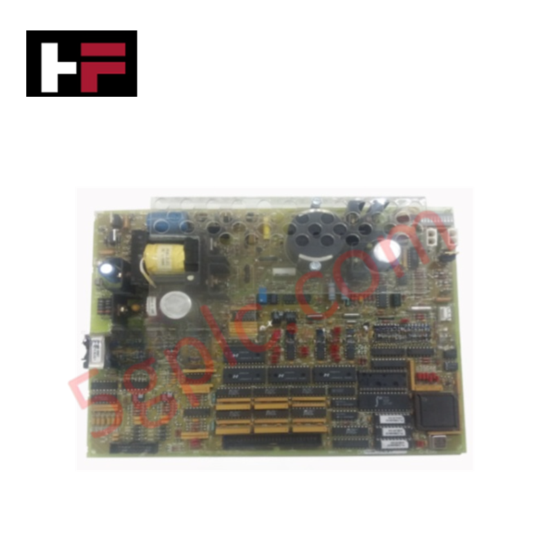
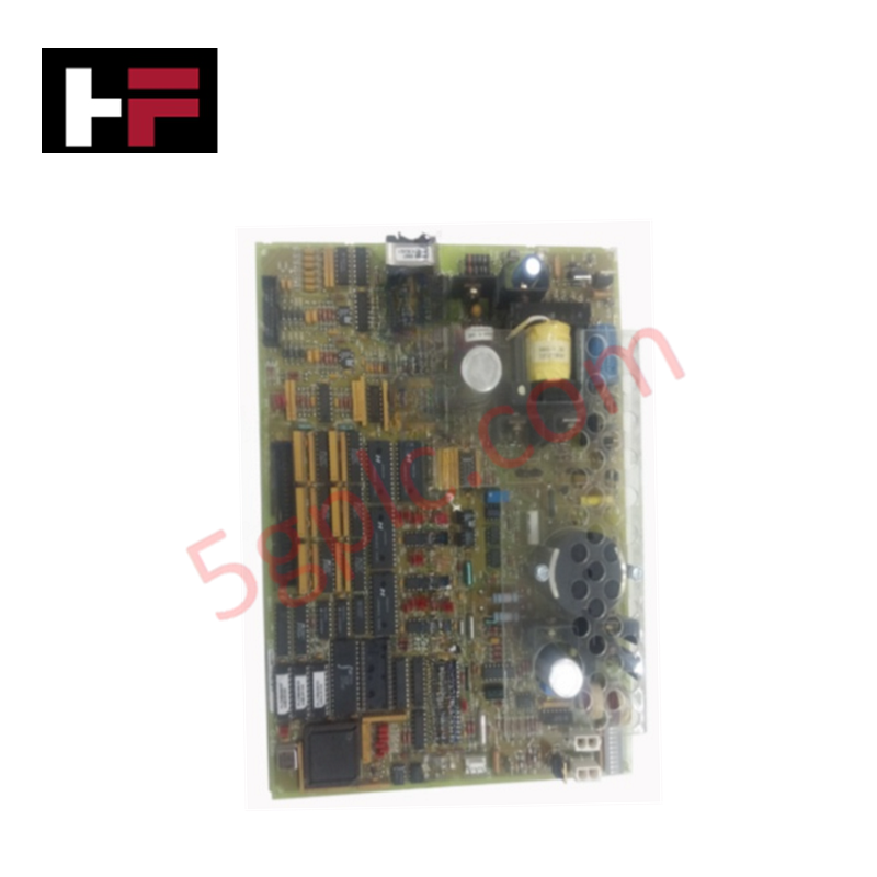
Configured for turbine protection and trip execution within Mark V Speedtronic control systems, the GE DS200TCEAG1BSF (DS200TCEAG1B Emergency Over Speed Board) provides direct physical signal monitoring for over-speed and flame detection states.
Hardware Specifications
| Parameter | Specification |
|---|---|
| Model | DS200TCEAG1BSF |
| Brand | General Electric |
| Origin | USA |
| Weight | 0.8 kg |
| Dimensions | 16 cm x 16 cm x 12 cm |
| Core Function | Over-speed and flame detection monitoring |
| Connectivity | Pair of bayonet connectors |
Industrial Control & Firmware Compatibility
The DS200TCEAG1BSF utilizes an onboard microprocessor and multiple programmable read-only memory (PROM) modules to execute protective trip logic. For seamless system integration, ensure that the board's firmware version is compatible with the existing Mark V control processor revision, as mismatched firmware can lead to initialization errors or incorrect trip setpoints. The board’s I/O density scaling relies on the 30 onboard jumpers, which must be configured to match the specific turbine speed and flame detection parameters of the installation. Backplane bus communication velocity must remain within the design limits of the Mark V architecture to ensure deterministic response times during emergency shutdown events.
Frequently Asked Questions
Q: How is the trip condition signaled to the rest of the drive?
A: The board monitors inputs for over-speed and flame detection conditions. Upon detection of a trip state, the board executes a shutdown sequence by interfacing with the drive components via the integrated bayonet connectors.
Q: Is the jumper configuration user-modifiable?
A: The board contains 30 jumpers that are utilized for hardware-level configuration of speed thresholds and detection logic. These must be set according to the site-specific documentation; unauthorized changes may lead to improper trip behavior or failure to detect turbine over-speed conditions.
Field Installation Guidelines
- Connector Handling: The board utilizes bayonet-style connectors. When disconnecting, stabilize the board with one hand while applying axial force to the connector with the other. This prevents excessive torque or bending stresses on the female board-mounted connectors. Do not pull on the cable itself, as this can disconnect internal signal wires.
- Component Seating: Inspect all 30 jumpers for proper seating before installation. Vibration during turbine operation can cause loosely seated jumpers to lose contact, potentially triggering false trip signals or system diagnostic alarms.
- ESD Mitigation: As the board contains sensitive PROM modules and a dedicated microprocessor, utilize grounded wrist straps and ESD-safe surfaces during handling to prevent static damage to the internal logic components.
- Signal Verification: Prior to final commissioning, verify that the flame detection and speed signal inputs are properly shielded at the bayonet connector interface to minimize noise injection, which could interfere with the board's internal detection logic.
Additional Information
- 100% Genuine Parts: All products are original and authentic, ensuring reliable industrial performance.
- 30-Day Refund Guarantee: Return any in-stock item within 30 days in original, unopened packaging for a full refund (excluding shipping and fees).
- 12-Month Warranty: Covers defects in materials or workmanship; excludes misuse, normal wear, or unauthorized modifications.
- Worldwide Shipping: We ship via USPS, UPS, FedEx, and DHL. Delivery times vary by country and may be subject to customs or import fees.
- Support & Contact: Technical and warranty assistance is available anytime. Contact us here: Contact.
- Purchase Guidance: Check product specifications and compatibility carefully before ordering to ensure proper application.


Tech & Buying Guide

Redundant Automation Systems: Ensuring Continuous Uptime in Critical Control Infrastructure
System reliability directly determines operational profitability across high stakes process industries. Modern industrial automation platforms must eliminate single points of failure to prevent catastrophic shutdowns. Deploying fault tolerant architecture safeguards complex facilities against unexpected hardware glitches, network disruptions, and maintenance outages.

Understanding Types of Noise in Electronic Circuits and Control Systems
Signal integrity directly determines measurement accuracy and loop stability across industrial automation environments. Electronic noise introduces unwanted stochastic interference into analog loops, sensor feedback lines, and digital fieldbus networks. Understanding how intrinsic electronic noise and external electromagnetic interference manifest allows control engineers to optimize signal conditioning and shield sensitive instrumentation effectively.

Why 24V DC Power Supplies Standardize Modern Industrial Automation
Industrial control cabinets worldwide rely on 24V DC as the universal power standard for field instrumentation, sensors, and controllers. Walk into any manufacturing plant, and you will find PLCs, human-machine interfaces (HMIs), and smart actuators running on extra-low voltage DC. Standardizing on 24V DC enhances operational safety, lowers cabinet footprint, and maintains steady control performance across factory networks.