


Product Details
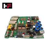
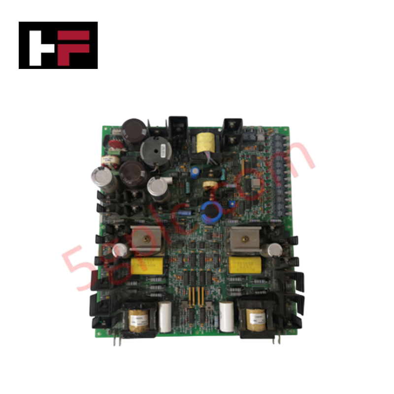
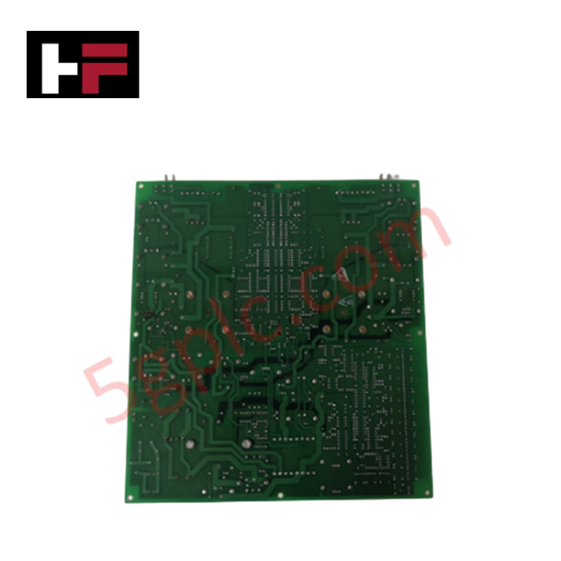
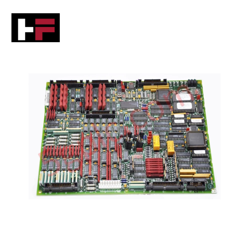
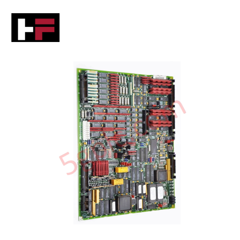
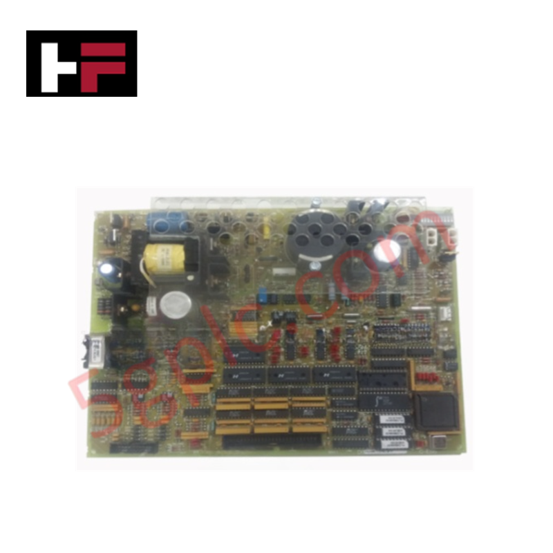
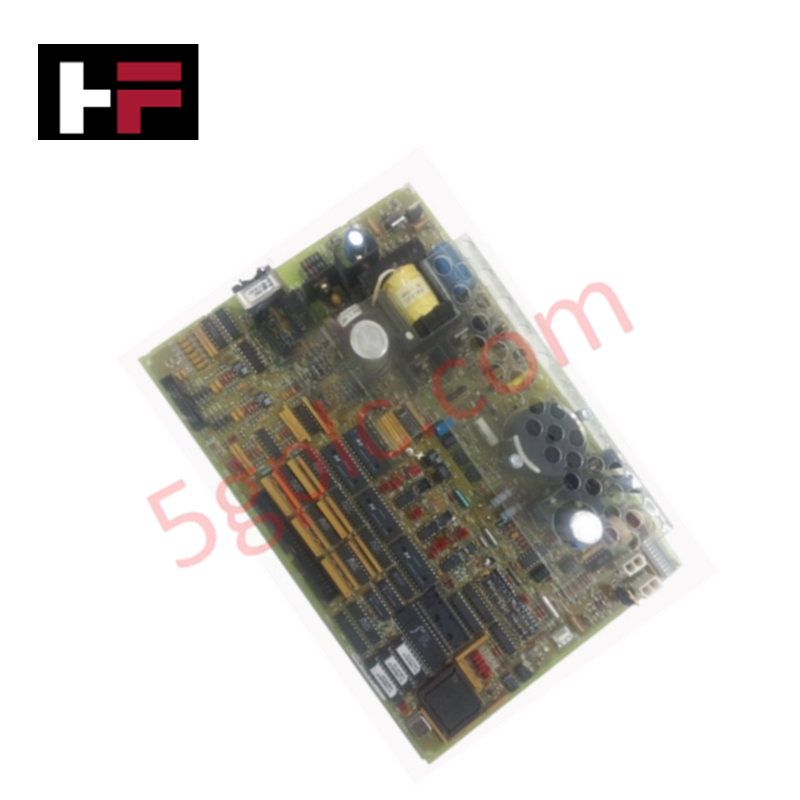
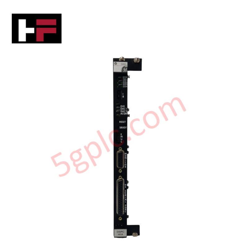
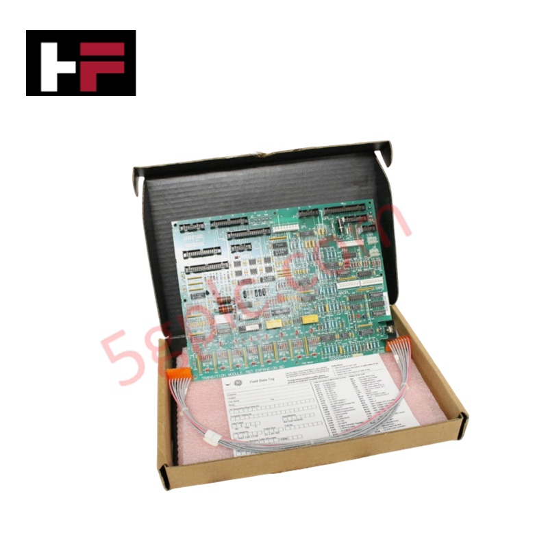
The General Electric DS200SDCIG1A, also cataloged as the DS200SDCIG1 DC Power Supply and Instrumentation Board, operates as a dedicated hardware component for power regulation and signal instrumentation within Mark V turbine control and DC2000 drive platforms.
Hardware Specifications
| Parameter | Specification |
|---|---|
| Model | DS200SDCIG1A |
| Brand | General Electric |
| Origin | USA |
| Dimensions | Standard Mark V PCB form factor |
| Operating Temp | Per standard industrial control specifications |
| Function | Instrumentation of armature/field current and voltage |
Industrial Control and Firmware Compatibility
The DS200SDCIG1A module interfaces with Mark V rack backplanes and DC2000 drive assemblies. It facilitates accurate monitoring of AC line and DC motor signals, including voltage magnitude and phase sequence parameters. The board architecture requires precise backplane bus communication velocity settings to ensure data synchronization with the primary controller. Firmware flash compatibility must be validated against the Mark V system processor revision to support the instrumentation logic inherent in the SDCI board. The design allows for I/O density scaling when integrating multiple boards within the drive control loop.
Frequently Asked Questions
Q: Does the board support on-line hot-swapping?
A: No. All electrical current must be removed from the drive cabinet and sufficient discharge time allowed before board removal. Hot-swapping is restricted due to potential high-voltage exposure.
Q: How is signal instrumentation handled on the board?
A: The board features integrated circuits designed to instrument armature and field current and voltage signals. Status is monitored via individual LED indicators mapped to the fuse components for immediate fault diagnostics.
Field Installation Guidelines
- Safety Compliance: Ensure total isolation of the DC drive power supply before cabinet entry. Verify the absence of voltage using a calibrated multimeter.
- Component Handling: When removing or installing, minimize contact with plastic snaps, panels, and adjacent PCBs to prevent physical damage.
- Cable Disconnection: When separating ribbon cables, apply pressure to both connector bodies simultaneously. Do not pull directly on the ribbon cable to avoid pin misalignment or conductor fracture.
- Wiring Inspection: In the event of a blown fuse (indicated by LED), inspect the local wiring for short circuits or insulation degradation prior to replacing the fuse or the board.
- Grounding: Maintain secure mounting to the chassis using all available hardware to ensure the PCB maintains a common reference potential for instrumentation accuracy.
Additional Information
- 100% Genuine Parts: All products are original and authentic, ensuring reliable industrial performance.
- 30-Day Refund Guarantee: Return any in-stock item within 30 days in original, unopened packaging for a full refund (excluding shipping and fees).
- 12-Month Warranty: Covers defects in materials or workmanship; excludes misuse, normal wear, or unauthorized modifications.
- Worldwide Shipping: We ship via USPS, UPS, FedEx, and DHL. Delivery times vary by country and may be subject to customs or import fees.
- Support & Contact: Technical and warranty assistance is available anytime. Contact us here: Contact.
- Purchase Guidance: Check product specifications and compatibility carefully before ordering to ensure proper application.
Tech & Buying Guide

Essential SCADA Features for Modern IoT-Enabled Industrial Automation
The convergence of traditional SCADA systems with the Industrial Internet of Things (IIoT) has redefined factory automation. Choosing a robust platform requires more than just standard monitoring capabilities. In this era of Industry 4.0, your supervisory system must bridge the gap between legacy control systems and enterprise-level data integration.

Selecting Rockwell Automation Allen-Bradley PLCs for Small and Mid-Sized Applications
Rockwell Automation remains a cornerstone in global industrial automation. Their Allen-Bradley brand provides a comprehensive portfolio of control systems designed to meet diverse production requirements. Choosing the right programmable logic controller (PLC) is critical for system reliability and scalability. This guide analyzes the Micro and Compact Logix families to help you select the optimal solution for small and medium-scale projects.

Strategic Selection: Choosing the Right SCADA Software for Your PLC Project
In industrial automation, the SCADA (Supervisory Control and Data Acquisition) system acts as the bridge between raw machine data and actionable human intelligence. Selecting the incorrect software platform can lead to integration bottlenecks, scalability issues, and excessive long-term maintenance costs. As an automation consultant with 15 years of experience, I have guided many projects through the selection process. Below are the essential criteria for choosing a platform that ensures both performance and longevity.