


Product Details
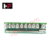
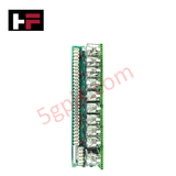
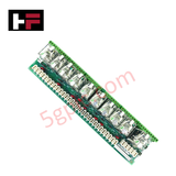
Configured for relay-based signal interfacing within Mark V Speedtronic control systems, the GE DS200RTBAG2AHC (DS200RTBAG2 Relay Terminal Board) provides direct physical electrical switching for LAN and remote I/O control applications.
Hardware Specifications
| Parameter | Specification |
|---|---|
| Model | DS200RTBAG2AHC |
| Brand | General Electric |
| Origin | USA |
| Weight | 0.8 kg |
| Dimensions | 16 cm x 16 cm x 12 cm |
| Operating Temp | Not specified |
| Power Consumption | 24 VDC (coil voltage) |
| Core Components | 7 DPDT (Form-C) relays, 3 4PDT relays, 10 MOV surge protectors |
Industrial Control & Firmware Compatibility
The DS200RTBAG2AHC functions as a passive interface module, requiring no firmware flash compatibility as it contains no logic-based software. Operational parameters are governed by board-level jumper configurations via berg-type jumper pins, which must be aligned with site-specific I/O requirements to ensure deterministic relay state execution. Backplane bus communication velocity is managed through the host interface, while the onboard diagnostic lamps provide real-time status indication of relay coil activation. The board utilizes MOV protection (130 V AC) for each relay to mitigate surge-induced damage, ensuring the module maintains its signal-switching integrity under inductive loading conditions.
Frequently Asked Questions
Q: Are the MOVs on the relay terminal board field-replaceable?
A: Yes. Each of the ten relays is protected by a 130 V AC metal oxide varistor (MOV). If a surge event occurs, these components are designed to be removed and replaced individually to restore relay protection without requiring a full board replacement.
Q: How do I select the correct relay terminal board for my application?
A: Selection is based on required coil voltage. The DS200RTBAG2AHC is rated for 24 VDC. For 110 VDC applications, specify the RTBAG1 board; for 115 VAC applications, specify the RTBAG3 board.
Field Installation Guidelines
- Relay Protection: Ensure that the MOVs are properly seated and intact prior to power-up. Damaged MOVs can lead to premature failure of the DPDT or 4PDT relay contacts due to high-voltage transients during inductive load switching.
- Jumper Configuration: Verify all berg-type jumper pin settings against the installation manual before initial energization. Incorrect jumper placement can lead to improper relay logic or feedback failures on the LAN/remote I/O circuit.
- Connector Integrity: The board features two stab connectors, one 16-pin connector, and one 2-pin inter-board connector. Ensure these are free of debris and fully engaged to prevent intermittent signal paths that could cause relay "chatter" or false state reporting.
- Shielding and Grounding: When terminating field wires, ensure proper cable management to avoid mechanical stress on the PCB. Verify that the cabinet ground connection is robust, as this board serves as a centralized relay termination point for sensitive control signals.
Additional Information
- 100% Genuine Parts: All products are original and authentic, ensuring reliable industrial performance.
- 30-Day Refund Guarantee: Return any in-stock item within 30 days in original, unopened packaging for a full refund (excluding shipping and fees).
- 12-Month Warranty: Covers defects in materials or workmanship; excludes misuse, normal wear, or unauthorized modifications.
- Worldwide Shipping: We ship via USPS, UPS, FedEx, and DHL. Delivery times vary by country and may be subject to customs or import fees.
- Support & Contact: Technical and warranty assistance is available anytime. Contact us here: Contact.
- Purchase Guidance: Check product specifications and compatibility carefully before ordering to ensure proper application.


Tech & Buying Guide

Redundant Automation Systems: Ensuring Continuous Uptime in Critical Control Infrastructure
System reliability directly determines operational profitability across high stakes process industries. Modern industrial automation platforms must eliminate single points of failure to prevent catastrophic shutdowns. Deploying fault tolerant architecture safeguards complex facilities against unexpected hardware glitches, network disruptions, and maintenance outages.

Understanding Types of Noise in Electronic Circuits and Control Systems
Signal integrity directly determines measurement accuracy and loop stability across industrial automation environments. Electronic noise introduces unwanted stochastic interference into analog loops, sensor feedback lines, and digital fieldbus networks. Understanding how intrinsic electronic noise and external electromagnetic interference manifest allows control engineers to optimize signal conditioning and shield sensitive instrumentation effectively.

Why 24V DC Power Supplies Standardize Modern Industrial Automation
Industrial control cabinets worldwide rely on 24V DC as the universal power standard for field instrumentation, sensors, and controllers. Walk into any manufacturing plant, and you will find PLCs, human-machine interfaces (HMIs), and smart actuators running on extra-low voltage DC. Standardizing on 24V DC enhances operational safety, lowers cabinet footprint, and maintains steady control performance across factory networks.