


Product Details
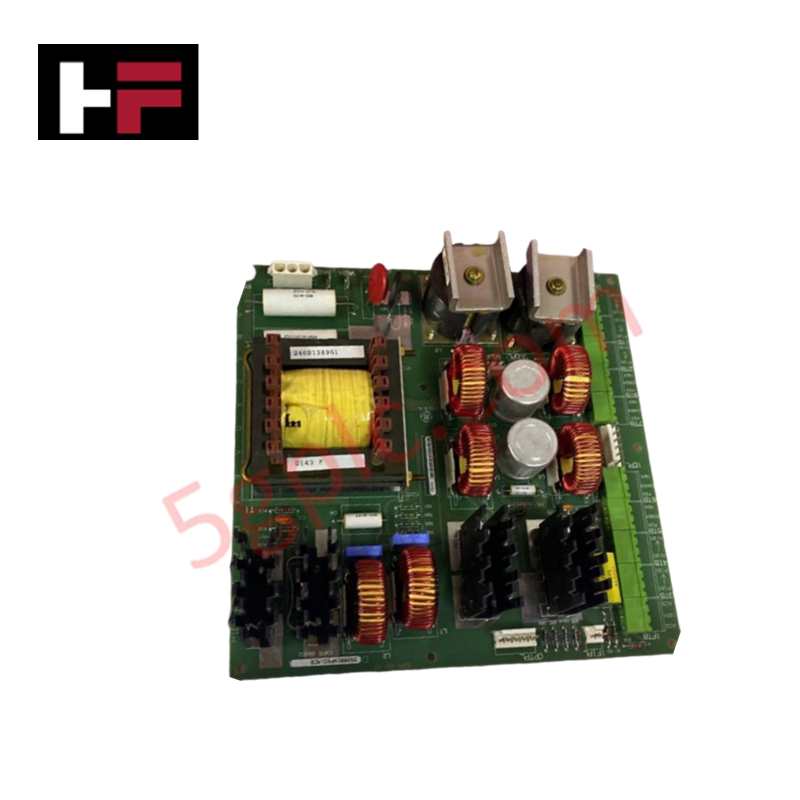
Configured for power regulation and system diagnostics within Mark V turbine control environments, the GE DS200EXPSG1ACB (DS200EXPSG1 Power Supply Board) provides direct physical electrical distribution and status monitoring.
Hardware Specifications
| Parameter | Specification |
|---|---|
| Model | DS200EXPSG1ACB |
| Brand | General Electric |
| Core Components | 1 LED, 3 fuses, 1 reset button, 3 9-pin connectors |
Industrial Control & Firmware Compatibility
The DS200EXPSG1ACB manages local power distribution utilizing a 5C060 programmable logic device to govern system regulation. For operational consistency, the board supports integration into the Mark V Speedtronic architecture, ensuring backplane bus communication velocity remains stable during high-demand turbine control cycles. The onboard diagnostic LED serves as a primary status indicator; steady green illumination confirms successful completion of power-on self-tests. While the board includes a Berg-type JP1 jumper for factory testing, it does not support field-configurable firmware flash updates; system logic remains fixed within the pre-programmed 5C060 device.
Frequently Asked Questions
Q: What does it indicate when the onboard green LED fails to illuminate?
A: A non-illuminated LED signifies that the board has not passed startup diagnostic tests or is experiencing a power fault. Technicians should utilize the designated onboard test points to verify individual circuit voltages as outlined in the GEI-100168 instruction manual.
Q: Can the JP1 jumper be modified to change board operation?
A: No. The JP1 Berg-type jumper is strictly for manufacturing test purposes. Any attempt to modify or move this jumper may disrupt the factory-set logic and is not permitted for field application.
Field Installation Guidelines
- Power Isolation: Before installation or removal, remove all power sources from the assembly. Verify zero voltage potential at all connection points to prevent damage to voltage-sensitive integrated circuits.
- Connector Management: Disconnect all 9-pin connectors in accordance with the sequences defined in the GEI-100168 technical manual. Ensure connectors are seated firmly upon reinstallation to prevent intermittent power fluctuations.
- Handling Precautions: The board contains sensitive surface-mount components. Handle by the edges or mounting hardware to avoid electrostatic discharge (ESD) or accidental contact with hazardous surface voltages present on the base PCB.
- Diagnostic Verification: Following installation, monitor the green LED status. Use the board's test points to validate that output voltage rails align with system requirements before restoring full control logic to the turbine processor.
Additional Information
- 100% Genuine Parts: All products are original and authentic, ensuring reliable industrial performance.
- 30-Day Refund Guarantee: Return any in-stock item within 30 days in original, unopened packaging for a full refund (excluding shipping and fees).
- 12-Month Warranty: Covers defects in materials or workmanship; excludes misuse, normal wear, or unauthorized modifications.
- Worldwide Shipping: We ship via USPS, UPS, FedEx, and DHL. Delivery times vary by country and may be subject to customs or import fees.
- Support & Contact: Technical and warranty assistance is available anytime. Contact us here: Contact.
- Purchase Guidance: Check product specifications and compatibility carefully before ordering to ensure proper application.


Tech & Buying Guide

Understanding Dry Contacts in PLC Wiring: An Industrial Automation Guide
Mastering contact switching principles is essential for reliable control panels. Field devices and PLCs interface through dry or wet contacts. This technical guide examines the mechanics of dry contacts, explores their wiring architectures, and evaluates their key advantages in industrial automation.

Ultimate Commissioning Checklist for Industrial Automation Systems: An Engineering Guide
Commissioning is the most decisive phase of an industrial automation project, transforming control hardware and software into an operational facility. Thorough testing prevents costly startup delays and builds customer confidence. This guide covers essential checklists, electrical standards, and best practices.

Redundant Automation Systems: Core Architecture, Business Value, and Technical Advantages
Unplanned downtime poses a major financial threat to process manufacturing. To prevent costly interruptions, engineers deploy redundant PLC and DCS architectures that ensure continuous operation when hardware fails. This technical guide explores redundancy principles, critical system nodes, and real-world scenarios.