










Product Details
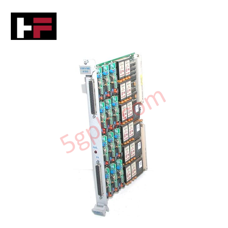
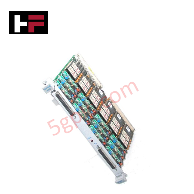
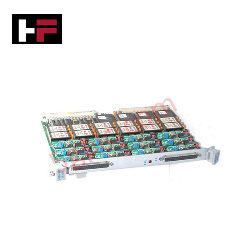
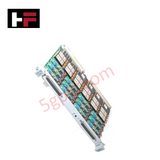
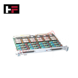
The GE VMIVME-4150 332-004150-201, also cataloged as the VMIVME4150 Analog Output PLC Board, operates as a dedicated hardware component for digital-to-analog signal conversion within VMEbus architecture platforms.
Hardware Specifications
| Parameter | Specification |
|---|---|
| Model | VMIVME-4150 332-004150-201 |
| Brand | GE Fanuc |
| Origin | United States |
| Weight | Standard Single Eurocard Weight |
| Dimensions | Single Eurocard Form Factor with Front Panel |
| Operating Temp | 0 - 60 deg C |
| Power Consumption | VMEbus Backplane Rails Dependent |
| Channels | 12 |
| Output Voltage Range | -10 V to +10 V |
| Accuracy | +/-0.1% of full scale |
| Isolation | 2 kV continuous isolation |
| Noise | <1 mV rms |
| Output Resolution | 12 bits |
| D/A Converter | Monolithic 12-bit D/A |
| Update Rate | 100 kHz |
I/O Density Scaling and Backplane Bus Communications
The hardware interfaces 12 high-precision analog channels across a single Eurocard slot to optimize I/O density scaling. The onboard architecture utilizes monolithic 12-bit digital-to-analog converters running at a 100 kHz update rate per channel to drive voltage loops with minimal propagation delay. To protect the backplane processing logic against common-mode electrical faults, the output circuitry incorporates 2 kV continuous electrical galvanic isolation, maintaining loop performance even under elevated noise conditions (<1 mV rms).
Frequently Asked Questions
Q: Does the VMIVME4150 board accommodate live insertion or extraction while the chassis is powered?
A: No. The standard parallel mechanical pin arrangement of the VMEbus interface on this module does not integrate staggered grounding lengths required for live swap operations. Removing or inserting the card under power will trigger bus faults or damage local component logic layers.
Q: How are manual trim modifications or hardware potentiometers bypassed during calibration?
A: The module relies on software-selectable output ranges and embedded calibration circuitry. Drift adjustments are addressed programmatically over the backplane bus, completely eliminating the need for component manual trimming.
Field Installation Guidelines
- Chassis Slot Placement: Align the PCB edges with the VME chassis card guides. Push smoothly until the pin headers mesh completely with the backplane connectors, then apply the front panel latching screws.
- Analog Cabling Isolation: Route the -10 V to +10 V signal paths through dedicated, grounded metallic conduits separate from high-current AC motor leads or switching control relays.
- Shield Grounding Framework: Fasten external twisted-pair instrument cable shields to a unified earth grounding point located strictly at the control cabinet entry bulkhead to eliminate circulating ground currents.
Additional Information
- 100% Genuine Parts: All products are original and authentic, ensuring reliable industrial performance.
- 30-Day Refund Guarantee: Return any in-stock item within 30 days in original, unopened packaging for a full refund (excluding shipping and fees).
- 12-Month Warranty: Covers defects in materials or workmanship; excludes misuse, normal wear, or unauthorized modifications.
- Worldwide Shipping: We ship via USPS, UPS, FedEx, and DHL. Delivery times vary by country and may be subject to customs or import fees.
- Support & Contact: Technical and warranty assistance is available anytime. Contact us here: Contact.
- Purchase Guidance: Check product specifications and compatibility carefully before ordering to ensure proper application.


Tech & Buying Guide

Demystifying the DDE Protocol in Legacy Industrial Automation Systems
Modern control systems rely heavily on seamless interprocess communication to exchange operational data between software programs. Microsoft first introduced the Dynamic Data Exchange (DDE) protocol in 1987 to enable real-time data sharing. In factory automation, DDE served as an early bridge between control software and Windows desktop applications. Therefore, understanding DDE mechanics provides crucial insights into how legacy industrial networks established software-level connectivity.

Demystifying CPU Communication Ports in Siemens PLC Architectures
Industrial automation relies heavily on robust data exchange between devices. Without seamless connectivity, field instruments, network switches, human-machine interfaces, and programmable logic controllers cannot coordinate effectively. Therefore, understanding the various CPU communication ports available in Siemens hardware ensures efficient factory automation design and seamless system integration.

Mastering the Siemens PLC Scan Cycle: How the CPU Executes Automation Programs
Industrial automation relies heavily on programmable logic controllers (PLCs) to manage complex manufacturing processes. Many engineers dive straight into programming without mastering the underlying architecture. However, understanding how a PLC CPU executes a program ensures reliable system design. Therefore, mastering the scan cycle optimizes both performance and troubleshooting in modern control systems.