


Product Details
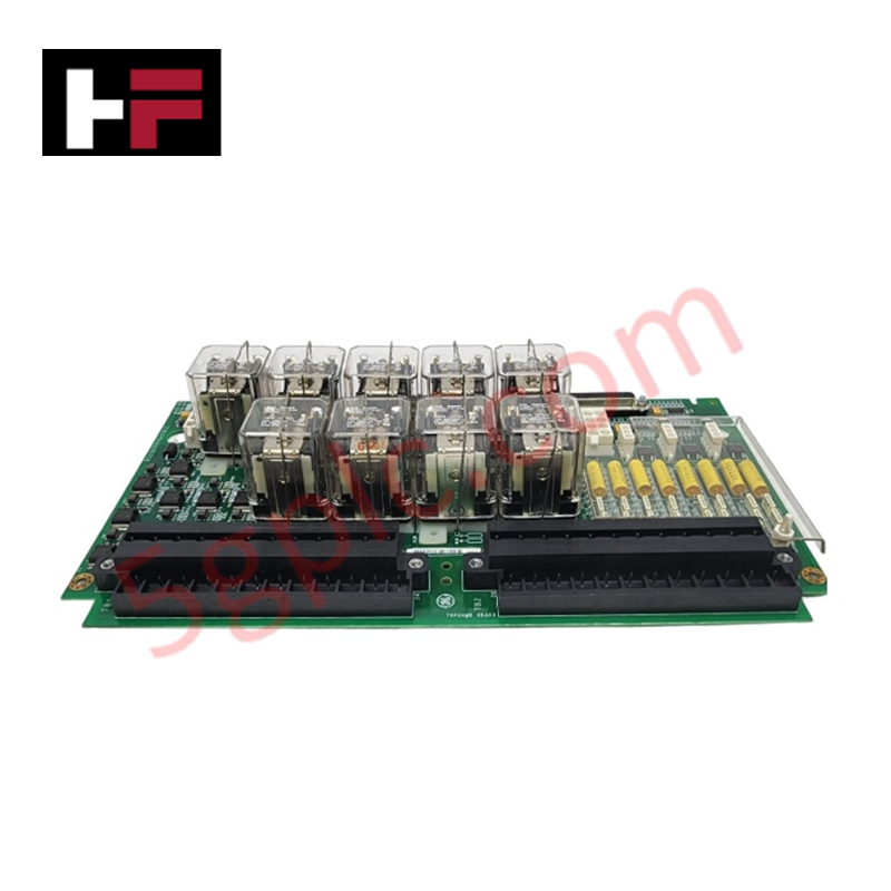
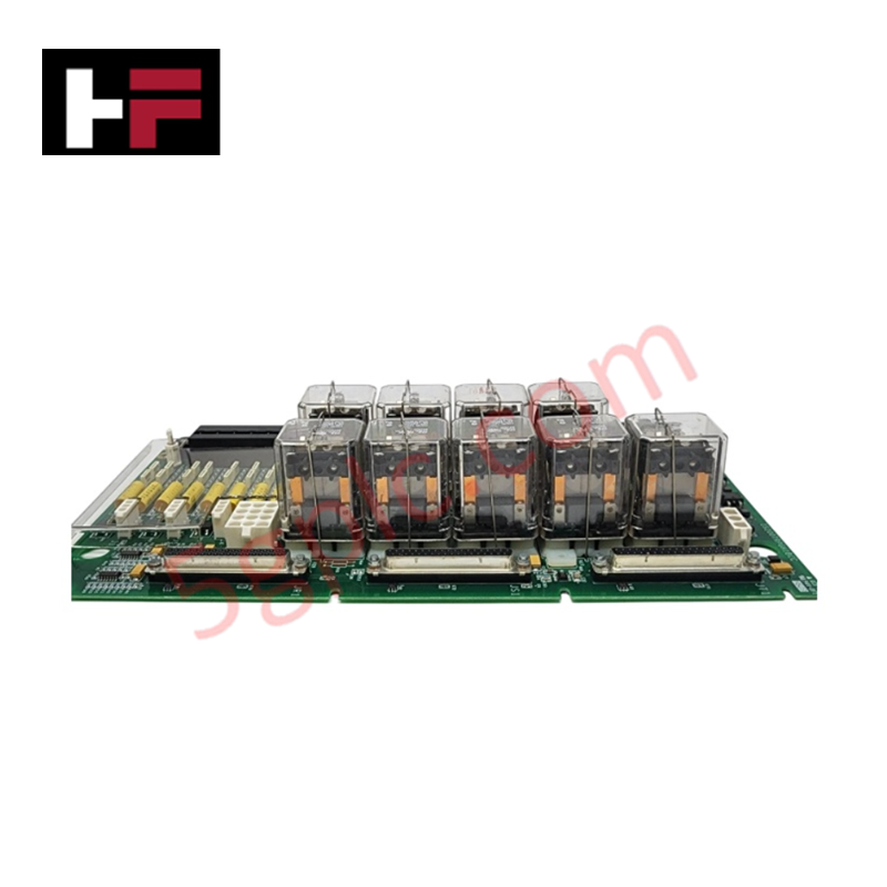
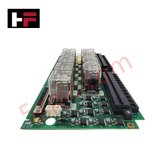
The General Electric IS200TRPGH1B, also cataloged as the IS200TRPGH1B Terminal Board, operates as a dedicated hardware component for turbine safety and trip logic execution within Mark VI control platforms. This board provides direct physical execution of solenoid interfacing, flame detection signal conditioning, and voting circuit management, ensuring deterministic trip response in gas turbine control architectures.
Hardware Specifications
| Parameter | Specification |
|---|---|
| Model | IS200TRPGH1B |
| Brand | General Electric |
| Origin | United States |
| Dimensions | Standard terminal board form factor |
| Operating Temp | Standard industrial ambient range |
| Power Consumption | 28 V (relay coil); 125 V dc (solenoid) |
| Trip Solenoids | 3 |
| Flame Detectors | 8 (Geiger-Mueller type) |
TMR Voting Architecture and Trip Logic
The IS200TRPGH1B employs a TMR (triple modular redundancy) 2oo3 architecture to ensure high-integrity trip execution. The board integrates nine magnetic relays arranged into three voting circuits, which interface directly with three trip solenoids, also known as Electrical Trip Devices (ETD). This redundant configuration ensures that the safety mechanism remains operational even in the event of a single-point component failure. Current suppression is managed via onboard metal oxide varistors (MOV) to mitigate inductive surges during solenoid de-energization. For flame monitoring, the board accepts inputs from up to eight Geiger-Mueller detectors, requiring a specialized 335 V dc supply voltage. The TRPG works in conjunction with the TREG terminal board to form the complete primary and emergency interface for ETD systems.
Frequently Asked Questions
Q: Can the IS200TRPGH1B be used in simplex control applications?
A: No. The H1B version is specifically engineered for TMR applications with three voting relays per solenoid. Simplex applications require the H2A or H2B versions, which utilize a single relay per solenoid.
Q: What is the purpose of the metal oxide varistors (MOV) on this board?
A: The MOVs are installed to provide current suppression for the trip solenoids. They absorb high-voltage transients generated by the L/R time constant (0.1 sec) of the solenoid coils during rapid shut-off sequences.
Field Installation Guidelines
- Mounting: Secure the board to the cabinet standoffs. Ensure all electrical terminals are accessible for wiring and diagnostic probing.
- Wiring: Maintain strict segregation between high-voltage flame detector lines (335 V dc) and low-voltage control signals (28 V). Use shielded cabling for all detector inputs to prevent noise-induced false flames.
- Solenoid Connections: Verify that the 125 V dc supply lines to the trip solenoids are properly fused at the source. Ensure torque requirements for terminal block screws are met to prevent high-resistance connections that could lead to intermittent solenoid response.
- Grounding: Terminate all cable shields to the cabinet ground bar at the point of entry. Do not daisy-chain shields between terminal boards; each signal path must have a dedicated, low-impedance ground reference to ensure the integrity of the voting logic.
Additional Information
- 100% Genuine Parts: All products are original and authentic, ensuring reliable industrial performance.
- 30-Day Refund Guarantee: Return any in-stock item within 30 days in original, unopened packaging for a full refund (excluding shipping and fees).
- 12-Month Warranty: Covers defects in materials or workmanship; excludes misuse, normal wear, or unauthorized modifications.
- Worldwide Shipping: We ship via USPS, UPS, FedEx, and DHL. Delivery times vary by country and may be subject to customs or import fees.
- Support & Contact: Technical and warranty assistance is available anytime. Contact us here: Contact.
- Purchase Guidance: Check product specifications and compatibility carefully before ordering to ensure proper application.


Tech & Buying Guide

Redundant Automation Systems: Ensuring Continuous Uptime in Critical Control Infrastructure
System reliability directly determines operational profitability across high stakes process industries. Modern industrial automation platforms must eliminate single points of failure to prevent catastrophic shutdowns. Deploying fault tolerant architecture safeguards complex facilities against unexpected hardware glitches, network disruptions, and maintenance outages.

Understanding Types of Noise in Electronic Circuits and Control Systems
Signal integrity directly determines measurement accuracy and loop stability across industrial automation environments. Electronic noise introduces unwanted stochastic interference into analog loops, sensor feedback lines, and digital fieldbus networks. Understanding how intrinsic electronic noise and external electromagnetic interference manifest allows control engineers to optimize signal conditioning and shield sensitive instrumentation effectively.

Why 24V DC Power Supplies Standardize Modern Industrial Automation
Industrial control cabinets worldwide rely on 24V DC as the universal power standard for field instrumentation, sensors, and controllers. Walk into any manufacturing plant, and you will find PLCs, human-machine interfaces (HMIs), and smart actuators running on extra-low voltage DC. Standardizing on 24V DC enhances operational safety, lowers cabinet footprint, and maintains steady control performance across factory networks.