


Product Details
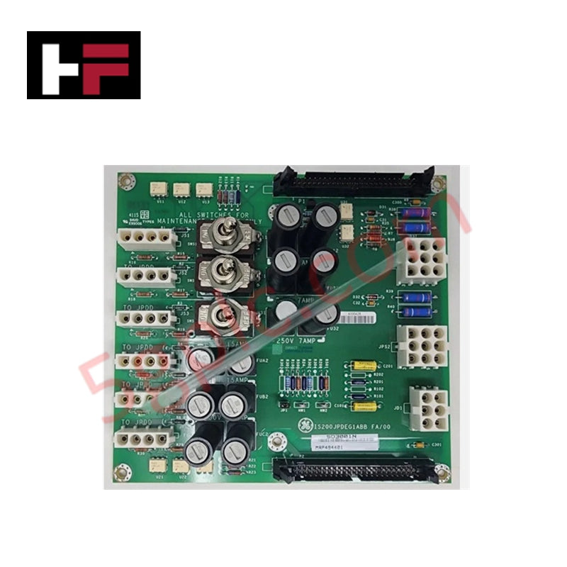
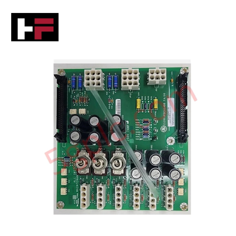
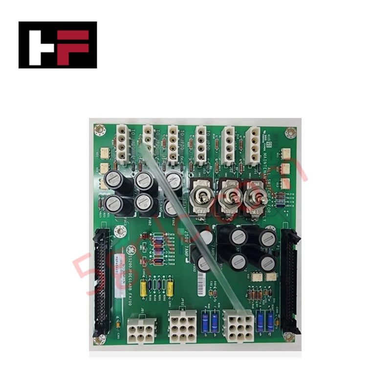
Configured for power management in Mark VIe turbine control systems, the GE IS200JPDEG1A (IS200JPDEG1A DC Battery Power Distribution Board) provides direct physical execution of DC power distribution to terminal board loads. This hardware component serves as the primary distribution interface within the PDM-style drive assembly, facilitating stable power delivery and diagnostic feedback signal transmission.
Hardware Specifications
| Parameter | Specification |
|---|---|
| Model | IS200JPDEG1A |
| Brand | GE |
| Dimensions | Includes integrated metal mounting bracket |
| Operating Temp | Standard industrial ambient range |
| Core Performance | 30 A input filter; DC circuit breaker; 2 x 50-pin diagnostic connectors |
Backplane Bus Communication and Deterministic Networks
The IS200JPDEG1A regulates backplane bus communication velocity and power delivery by interfacing with the PPDA Input/Output Pack. Connectivity is established through two 50-pin diagnostic connectors (P1 and P2), which facilitate real-time feedback signal transmission for system monitoring. The board includes a 30 A input filter and an integrated DC circuit breaker to maintain stable output profiles under varying load conditions. Firmware flash compatibility should be verified when replacing this revision A board to ensure that the logic governing the power distribution sequences remains aligned with the host Mark VIe controller firmware. Technicians must ensure that the communication path through the diagnostic connectors is free of impedance mismatches to maintain the accuracy of the feedback loops reported to the I/O packs.
Frequently Asked Questions
Q: Does the IS200JPDEG1A support hot-swapping during turbine operation?
A: No. The board is a power distribution component; it must be completely de-energized and isolated from the battery or power supply input before extraction to prevent electrical arcing or damage to the distribution circuitry.
Q: What is the function of the nine-pin Mate-n-lock connectors?
A: The two nine-pin Mate-n-lock connectors provide the primary DC power supply input to the board. Ensure these are securely latched to prevent intermittent power loss to downstream terminal boards.
Field Installation Guidelines
- Mounting: The board must be installed using the integrated metal mounting bracket within the PDM-style drive assembly. Verify that the bracket is securely fastened to the rack to provide both mechanical stability and the necessary path for the grounding output terminal.
- Grounding: Ensure the grounding output terminal on the metal bracket is bonded to the enclosure ground bus using a low-resistance conductor to mitigate common-mode noise.
- Wiring: Input power cabling connected to the Mate-n-lock connectors must be sized according to the 30 A current rating of the input filter. Avoid routing power supply leads near diagnostic signal paths to prevent induction of noise into the P1 and P2 feedback channels.
- Configuration: Use the onboard maintenance switches to isolate specific output circuits during service. Verify switch positions before applying input power to prevent inadvertent energization of downstream components.
Additional Information
- 100% Genuine Parts: All products are original and authentic, ensuring reliable industrial performance.
- 30-Day Refund Guarantee: Return any in-stock item within 30 days in original, unopened packaging for a full refund (excluding shipping and fees).
- 12-Month Warranty: Covers defects in materials or workmanship; excludes misuse, normal wear, or unauthorized modifications.
- Worldwide Shipping: We ship via USPS, UPS, FedEx, and DHL. Delivery times vary by country and may be subject to customs or import fees.
- Support & Contact: Technical and warranty assistance is available anytime. Contact us here: Contact.
- Purchase Guidance: Check product specifications and compatibility carefully before ordering to ensure proper application.


Tech & Buying Guide

Understanding Dry Contacts in PLC Wiring: An Industrial Automation Guide
Mastering contact switching principles is essential for reliable control panels. Field devices and PLCs interface through dry or wet contacts. This technical guide examines the mechanics of dry contacts, explores their wiring architectures, and evaluates their key advantages in industrial automation.

Ultimate Commissioning Checklist for Industrial Automation Systems: An Engineering Guide
Commissioning is the most decisive phase of an industrial automation project, transforming control hardware and software into an operational facility. Thorough testing prevents costly startup delays and builds customer confidence. This guide covers essential checklists, electrical standards, and best practices.

Redundant Automation Systems: Core Architecture, Business Value, and Technical Advantages
Unplanned downtime poses a major financial threat to process manufacturing. To prevent costly interruptions, engineers deploy redundant PLC and DCS architectures that ensure continuous operation when hardware fails. This technical guide explores redundancy principles, critical system nodes, and real-world scenarios.