










Product Details
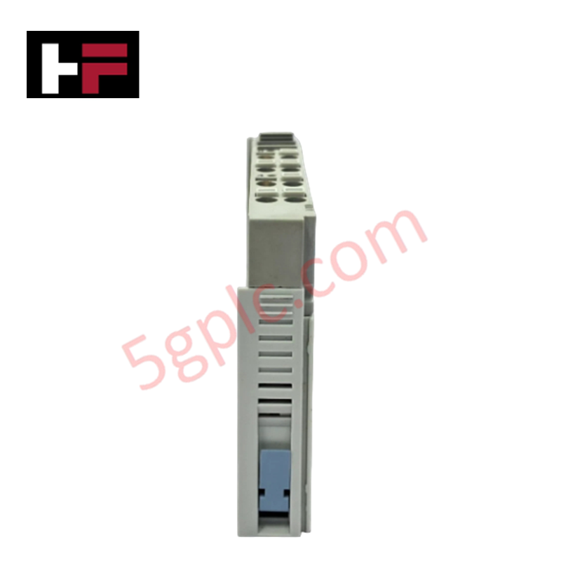
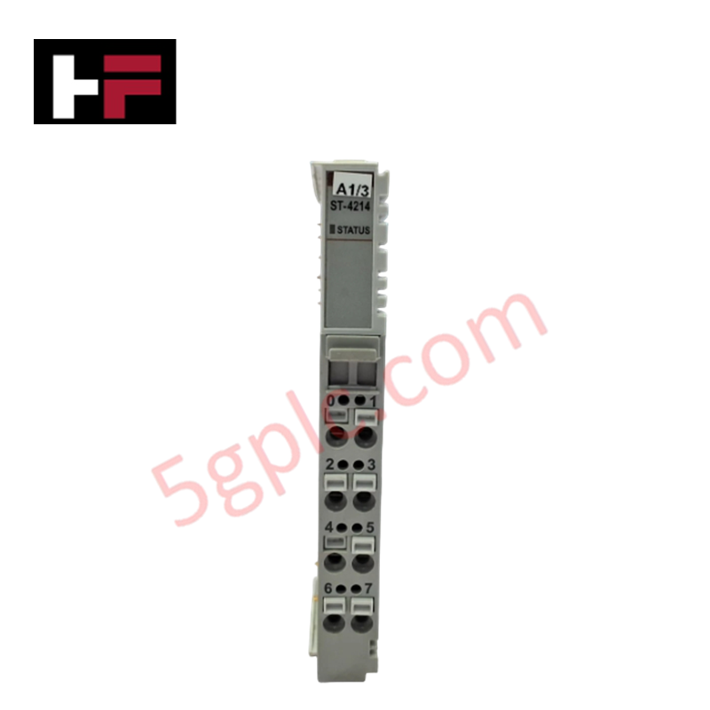
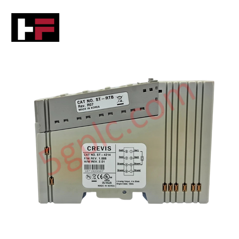
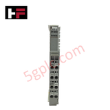
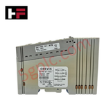
Configured for multi-channel current signal translation within RSTi PacSystem architectures, the GE ST-3218 (ST-3218 Analog Input Module) provides direct physical/electrical execution.
Hardware Specifications
| Parameter | Specification |
|---|---|
| Model | ST-3218 |
| Brand | GE Fanuc Emerson |
| Origin | United States |
| Weight | 0.91 kg (2.00 lbs) |
| Dimensions | 70 mm x 12 mm x 90 mm |
| Operating Temp | 0 - 60 deg C |
| Power Consumption | Max 60 mA @ 5 VDC (internal logic) |
| Inputs | 8 Analog Inputs |
| Resolution | 12 bits |
| Input Current Range | 4 to 20 mA |
| Input Impedance | 120 Ohms |
| Input Points per Common | 8 |
| Update Rate | 4 ms for all channels |
| Mounting | Rack or Panel |
Firmware Flash Compatibility and Internal Bus Processing
The module converts 8 independent 4-20 mA current loops using a localized 12-bit analog-to-digital converter array running a fixed 4 ms update loop across all channels. Internal logic relies on an instrumentation path with a precise 120 Ohms input impedance to manage loops while preserving signal linearity. Synchronous transmission across the local interface stack requires matching firmware flash compatibility structures to execute real-time register updates over Profinet / EtherNet/IP deterministic networks without introducing transport frame drops.
Frequently Asked Questions
Q: Does the ST-3218 module accommodate live insertion or extraction during system operation?
A: No. The parallel backplane design of the RSTi PacSystem slice interface does not feature staggered power pins or physical isolation gates. Performing a hot-swap operation while the terminal assembly is energized can cause unexpected logic faults or hardware component damage.
Q: How is the reference structure configured for the 8 loop circuits?
A: The hardware routes all 8 analog input loops through a single common point. All 4-20 mA field transmitters wired to this block must share the identical electrical ground potential to prevent parasitic ground loop measurement offset errors.
Field Installation Guidelines
- Base Rails Engagement: Mount the module into the designated base unit slots, keeping precise alignment along the terminal channel guides until the latching mechanism clicks into position.
- Current Loop Separation: Route all 4-20 mA field signal conductors through separate low-voltage wireways isolated from alternating current (AC) power lines and motor drive paths.
- Shielding Ground Plane: Connect instrument cable shields to a dedicated ground busbar directly at the point of enclosure entry, maintaining structural isolation from active neutral rails.
Additional Information
- 100% Genuine Parts: All products are original and authentic, ensuring reliable industrial performance.
- 30-Day Refund Guarantee: Return any in-stock item within 30 days in original, unopened packaging for a full refund (excluding shipping and fees).
- 12-Month Warranty: Covers defects in materials or workmanship; excludes misuse, normal wear, or unauthorized modifications.
- Worldwide Shipping: We ship via USPS, UPS, FedEx, and DHL. Delivery times vary by country and may be subject to customs or import fees.
- Support & Contact: Technical and warranty assistance is available anytime. Contact us here: Contact.
- Purchase Guidance: Check product specifications and compatibility carefully before ordering to ensure proper application.


Tech & Buying Guide

Demystifying the DDE Protocol in Legacy Industrial Automation Systems
Modern control systems rely heavily on seamless interprocess communication to exchange operational data between software programs. Microsoft first introduced the Dynamic Data Exchange (DDE) protocol in 1987 to enable real-time data sharing. In factory automation, DDE served as an early bridge between control software and Windows desktop applications. Therefore, understanding DDE mechanics provides crucial insights into how legacy industrial networks established software-level connectivity.

Demystifying CPU Communication Ports in Siemens PLC Architectures
Industrial automation relies heavily on robust data exchange between devices. Without seamless connectivity, field instruments, network switches, human-machine interfaces, and programmable logic controllers cannot coordinate effectively. Therefore, understanding the various CPU communication ports available in Siemens hardware ensures efficient factory automation design and seamless system integration.

Mastering the Siemens PLC Scan Cycle: How the CPU Executes Automation Programs
Industrial automation relies heavily on programmable logic controllers (PLCs) to manage complex manufacturing processes. Many engineers dive straight into programming without mastering the underlying architecture. However, understanding how a PLC CPU executes a program ensures reliable system design. Therefore, mastering the scan cycle optimizes both performance and troubleshooting in modern control systems.