


Product Details
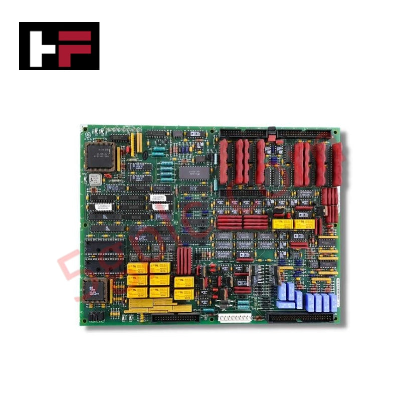
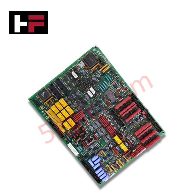
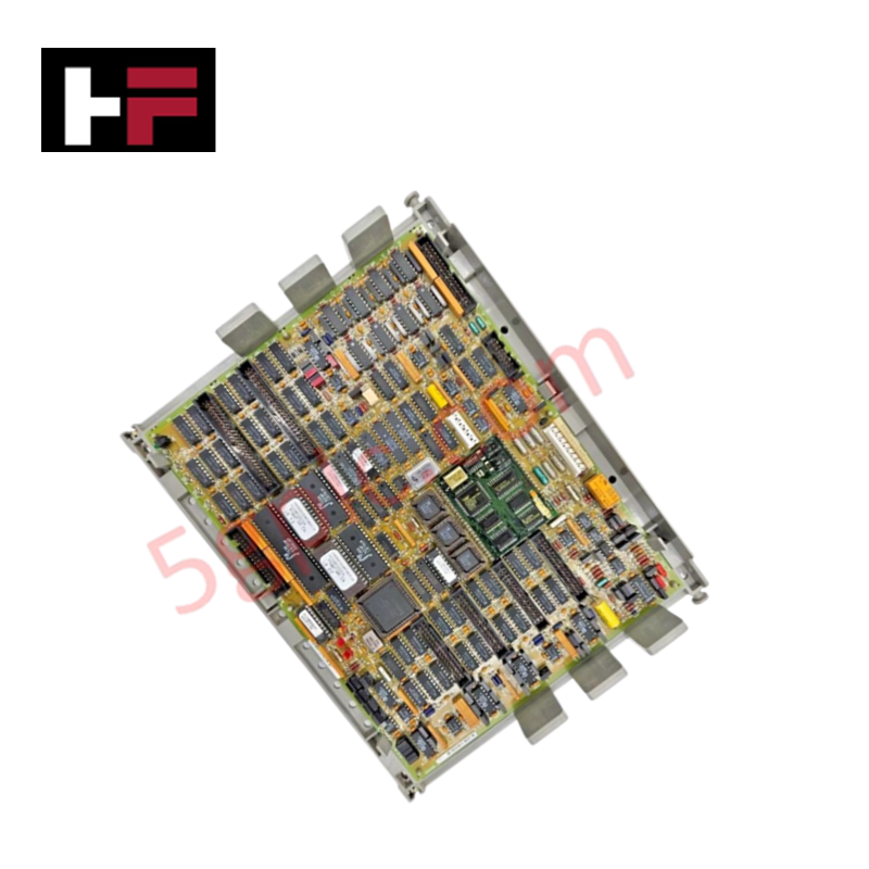
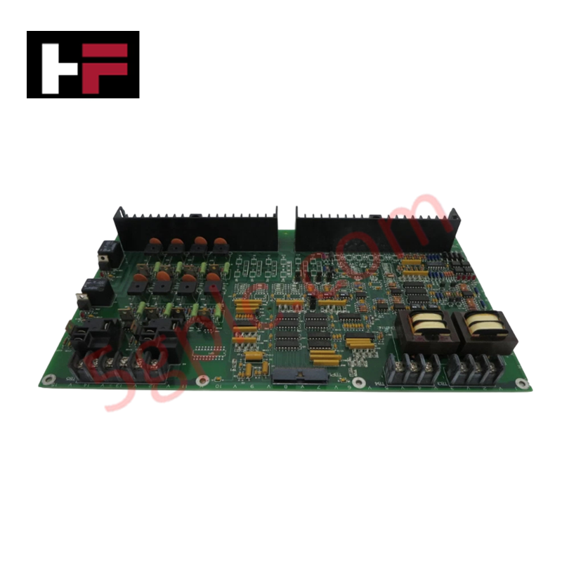
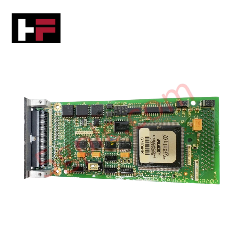
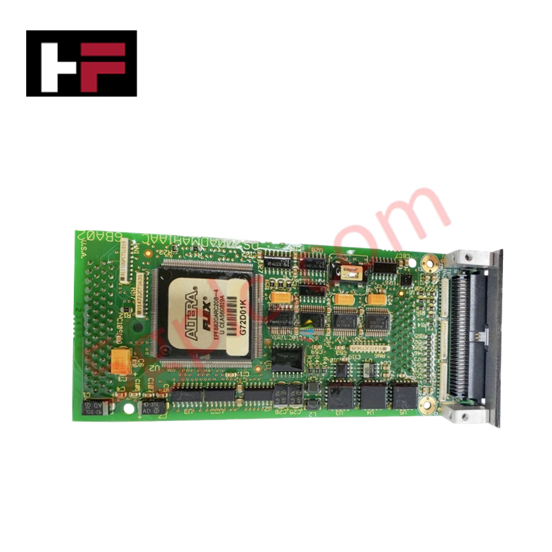
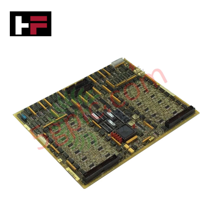
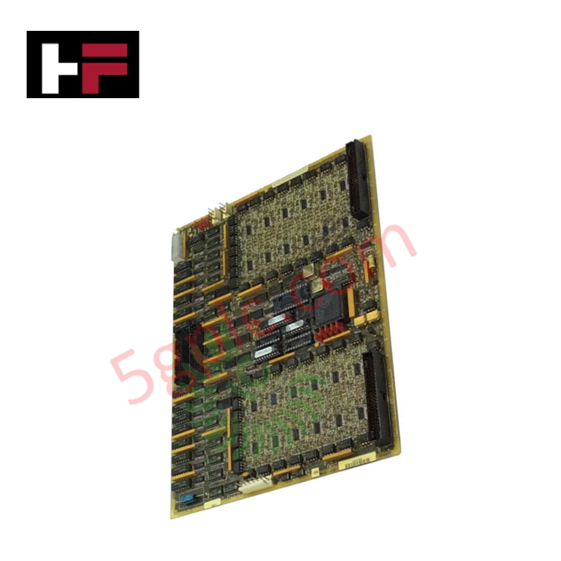
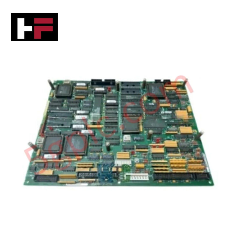
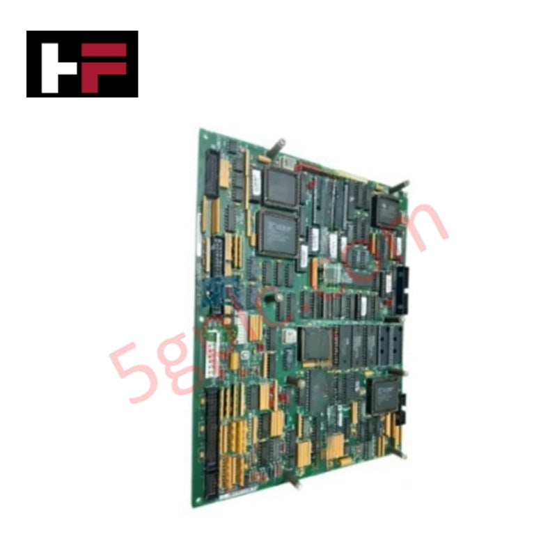
Configured for signal expansion and circuit regulation in Mark V turbine control systems, the GE DS200TCQFG1A (DS200TCQF Analog I/O Extension Card) provides direct physical execution of circuit switching and status monitoring.
Hardware Specifications
| Parameter | Specification |
|---|---|
| Model | DS200TCQFG1A |
| Brand | General Electric |
| Origin | USA |
| Operating Temp | Standard industrial range |
| Power Consumption | Not specified |
| Connectors | 2 x 50-pin (JUU, JB), 1 x 34-pin (JA), 1 x 9-pin |
| Status Indicators | 6 x Horizontal green LEDs |
Backplane Bus Communication and Deterministic Processing
The DS200TCQFG1A employs onboard electronic relays to facilitate circuit switching during routine processing cycles. These relays utilize soldered wire leads to maintain mechanical connection stability within the board assembly. The module interfaces with the control cabinet backplane via a 34-pin connector (JA) and two 50-pin connectors (JUU, JB). Deterministic I/O status is verified through 6 horizontally positioned LEDs, which illuminate green when power is applied and the respective logic functions are operating within nominal parameters. These indicators serve as the primary diagnostic interface for verifying backplane bus communication velocity and operational status during active processing.
Frequently Asked Questions
Q: Are the soldered relay wire leads field-replaceable?
A: No. The relays and their wire leads are factory-soldered to the PCB assembly. Attempting to repair or replace these components in the field risks damaging the circuit traces and compromising the structural integrity of the board.
Q: What is the significance of the 6 green LEDs on the board face?
A: Each LED corresponds to a specific I/O function or power rail. A green, illuminated LED indicates that the assigned function is receiving power and operating within normal design limits. If an LED is dark, it signals a loss of power or a failure in the corresponding circuit.
Field Installation Guidelines
- Ensure the Mark V control rack is de-energized before inserting the DS200TCQFG1A card to prevent electrical transients from damaging the I/O connectors.
- Verify that all 50-pin and 34-pin cable assemblies are correctly oriented and fully seated in their respective ports (JUU, JB, JA) to ensure reliable signal transmission.
- Handle the board by its edges or faceplate to protect the soldered relay leads from mechanical stress and to prevent electrostatic discharge damage.
- After installation, observe the horizontal LED array; all 6 LEDs must be green to confirm correct power distribution and functional synchronization with the drive control system.
Additional Information
- 100% Genuine Parts: All products are original and authentic, ensuring reliable industrial performance.
- 30-Day Refund Guarantee: Return any in-stock item within 30 days in original, unopened packaging for a full refund (excluding shipping and fees).
- 12-Month Warranty: Covers defects in materials or workmanship; excludes misuse, normal wear, or unauthorized modifications.
- Worldwide Shipping: We ship via USPS, UPS, FedEx, and DHL. Delivery times vary by country and may be subject to customs or import fees.
- Support & Contact: Technical and warranty assistance is available anytime. Contact us here: Contact.
- Purchase Guidance: Check product specifications and compatibility carefully before ordering to ensure proper application.
Tech & Buying Guide

Essential SCADA Features for Modern IoT-Enabled Industrial Automation
The convergence of traditional SCADA systems with the Industrial Internet of Things (IIoT) has redefined factory automation. Choosing a robust platform requires more than just standard monitoring capabilities. In this era of Industry 4.0, your supervisory system must bridge the gap between legacy control systems and enterprise-level data integration.

Selecting Rockwell Automation Allen-Bradley PLCs for Small and Mid-Sized Applications
Rockwell Automation remains a cornerstone in global industrial automation. Their Allen-Bradley brand provides a comprehensive portfolio of control systems designed to meet diverse production requirements. Choosing the right programmable logic controller (PLC) is critical for system reliability and scalability. This guide analyzes the Micro and Compact Logix families to help you select the optimal solution for small and medium-scale projects.

Strategic Selection: Choosing the Right SCADA Software for Your PLC Project
In industrial automation, the SCADA (Supervisory Control and Data Acquisition) system acts as the bridge between raw machine data and actionable human intelligence. Selecting the incorrect software platform can lead to integration bottlenecks, scalability issues, and excessive long-term maintenance costs. As an automation consultant with 15 years of experience, I have guided many projects through the selection process. Below are the essential criteria for choosing a platform that ensures both performance and longevity.