


Product Details
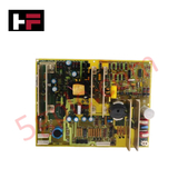
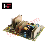
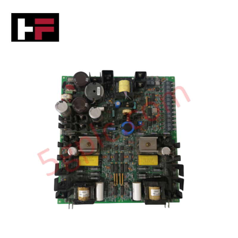
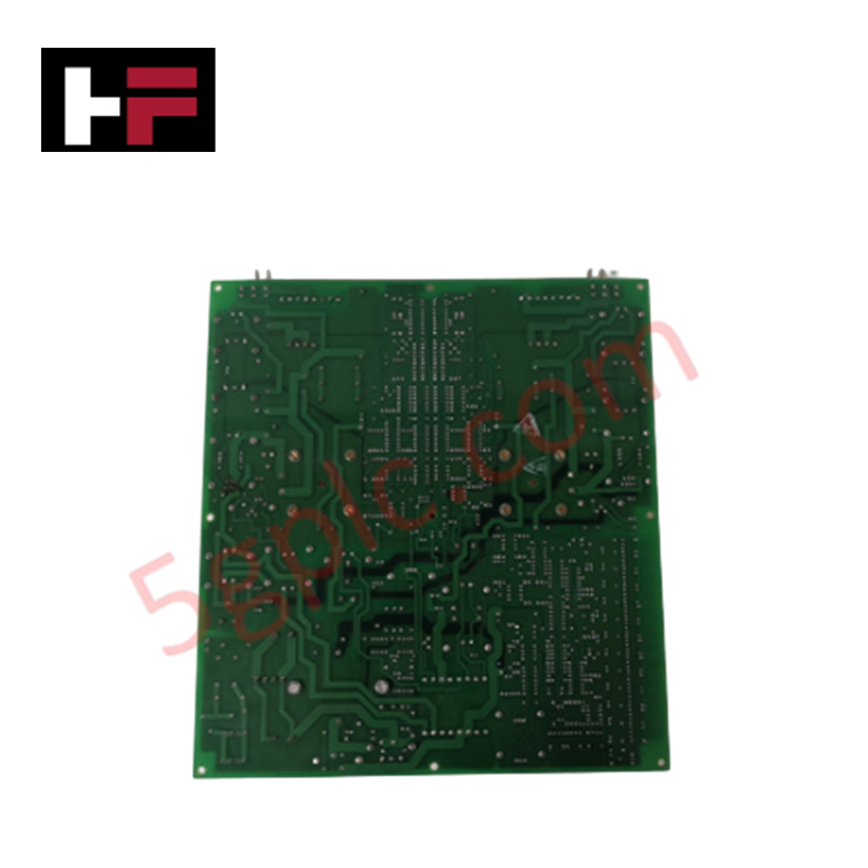
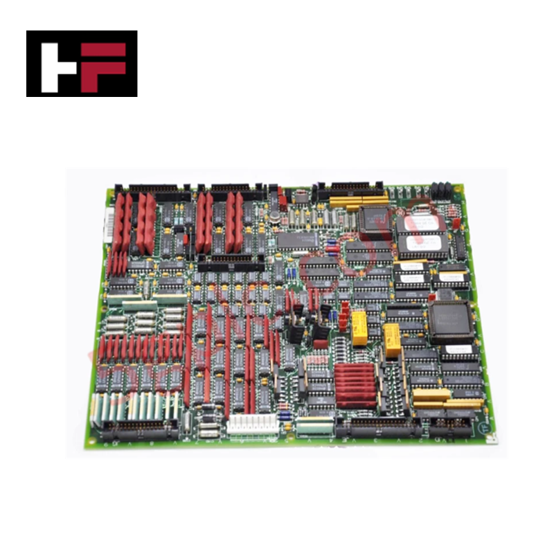
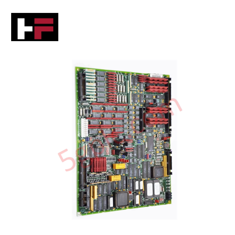
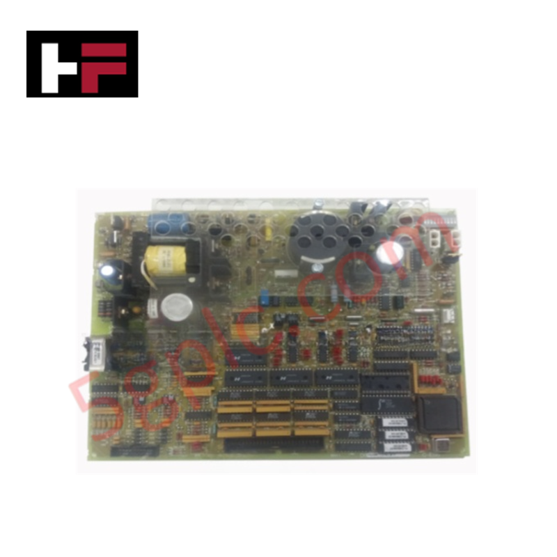
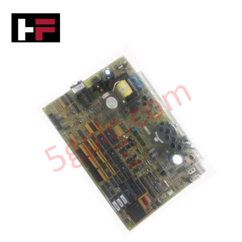
The GE DS200TCPSG1A, also cataloged as the DS200TCPS Power Supply Board, operates as a dedicated hardware component for converting 125 VDC input power into multiple regulated voltage levels within Mark V turbine control systems.
Hardware Specifications
| Parameter | Specification |
|---|---|
| Model | DS200TCPSG1A |
| Brand | General Electric |
| Origin | USA |
| Operating Temp | Standard industrial range |
| Power Consumption | N/A (Power supply unit) |
| Input Voltage | 125 VDC |
| Output Voltages | +5 VDC, +24 VDC, +/- 15 VDC, +/- 24 VDC |
Power Distribution and Deterministic Voltage Regulation
The DS200TCPSG1A is designed for deployment within R and I/O cores, providing essential power rails for microprocessor logic, RTD sensing, and servo valve current outputs. The board architecture features three onboard fuses for circuit protection and multiple test points for diagnostic monitoring of regulated outputs. Deterministic power delivery is maintained through physical connectors, including J1 for input power and 2PL, JC, JP1, and JP2 for daisy-chain distribution to peripheral boards such as AAHA, TCDA, and TCCA modules. The module operates without software configuration or hardware jumpers, ensuring consistent voltage output based on hardwired architecture.
Frequently Asked Questions
Q: Does the DS200TCPSG1A require field-level software configuration or jumper adjustments?
A: No. The board is designed as a plug-and-play power regulation module. It contains no software-configurable registers or hardware jumpers; all voltage transformation levels are fixed by the onboard circuitry.
Q: What are the primary diagnostic indicators available on the board?
A: The board features multiple test points for monitoring the +5 VDC, +24 VDC, and +/- 15/24 VDC output rails. If a specific voltage rail is absent, verify the integrity of the three onboard fuses and the 125 VDC input supply through connector J1.
Field Installation Guidelines
- Ensure the system rack is fully de-energized before inserting or removing the TCPS board to prevent arcing at the input and distribution connectors.
- Verify the 125 VDC input source at connector J1 prior to board activation to ensure the board operates within its design specifications.
- Handle the module by the edges and faceplate to maintain structural integrity of the daisy-chain distribution connectors (2PL, JC, JP1, JP2).
- After installation, utilize the integrated test points to confirm that all output voltage rails are within tolerance before re-establishing communication with the associated I/O and processor cores.
Additional Information
- 100% Genuine Parts: All products are original and authentic, ensuring reliable industrial performance.
- 30-Day Refund Guarantee: Return any in-stock item within 30 days in original, unopened packaging for a full refund (excluding shipping and fees).
- 12-Month Warranty: Covers defects in materials or workmanship; excludes misuse, normal wear, or unauthorized modifications.
- Worldwide Shipping: We ship via USPS, UPS, FedEx, and DHL. Delivery times vary by country and may be subject to customs or import fees.
- Support & Contact: Technical and warranty assistance is available anytime. Contact us here: Contact.
- Purchase Guidance: Check product specifications and compatibility carefully before ordering to ensure proper application.
Tech & Buying Guide

Essential SCADA Features for Modern IoT-Enabled Industrial Automation
The convergence of traditional SCADA systems with the Industrial Internet of Things (IIoT) has redefined factory automation. Choosing a robust platform requires more than just standard monitoring capabilities. In this era of Industry 4.0, your supervisory system must bridge the gap between legacy control systems and enterprise-level data integration.

Selecting Rockwell Automation Allen-Bradley PLCs for Small and Mid-Sized Applications
Rockwell Automation remains a cornerstone in global industrial automation. Their Allen-Bradley brand provides a comprehensive portfolio of control systems designed to meet diverse production requirements. Choosing the right programmable logic controller (PLC) is critical for system reliability and scalability. This guide analyzes the Micro and Compact Logix families to help you select the optimal solution for small and medium-scale projects.

Strategic Selection: Choosing the Right SCADA Software for Your PLC Project
In industrial automation, the SCADA (Supervisory Control and Data Acquisition) system acts as the bridge between raw machine data and actionable human intelligence. Selecting the incorrect software platform can lead to integration bottlenecks, scalability issues, and excessive long-term maintenance costs. As an automation consultant with 15 years of experience, I have guided many projects through the selection process. Below are the essential criteria for choosing a platform that ensures both performance and longevity.