










Product Details
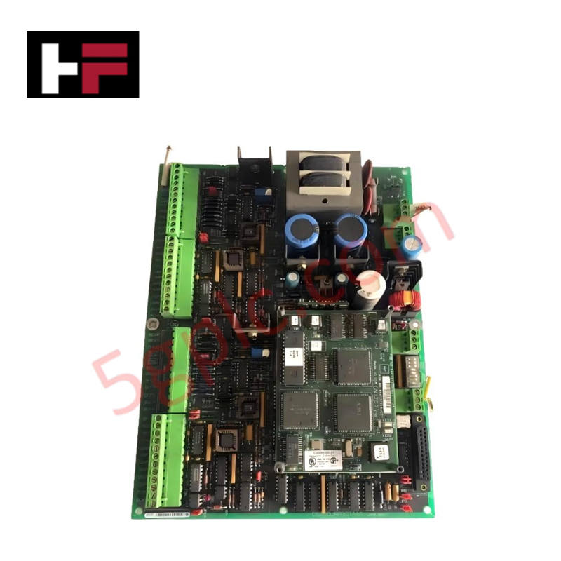
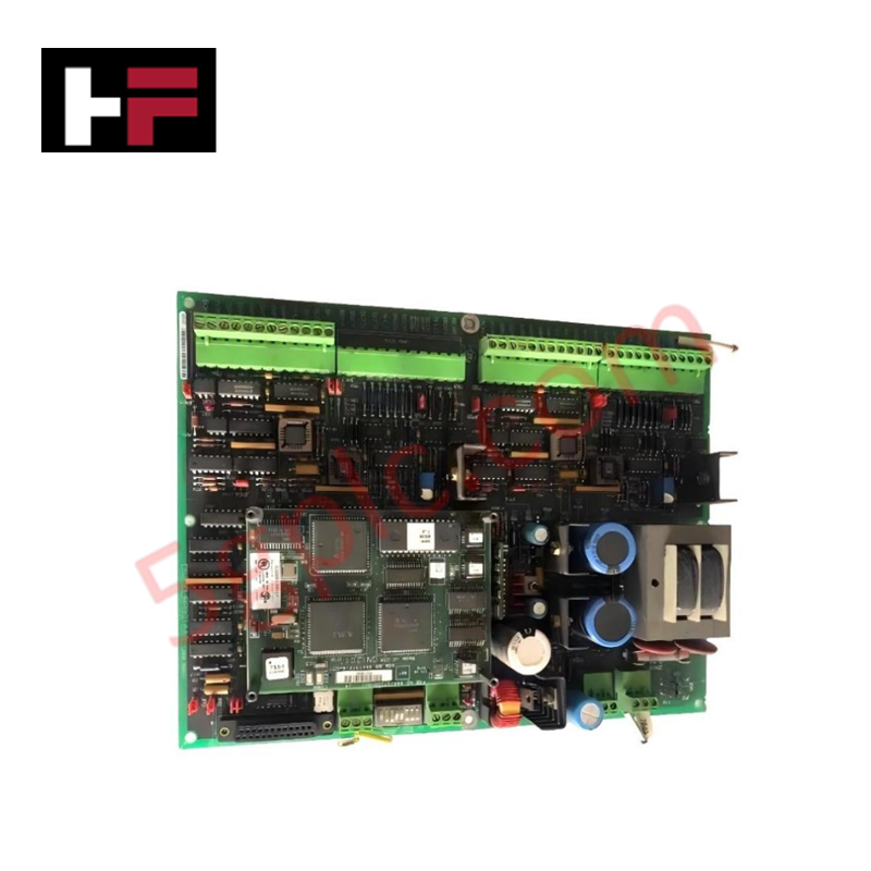
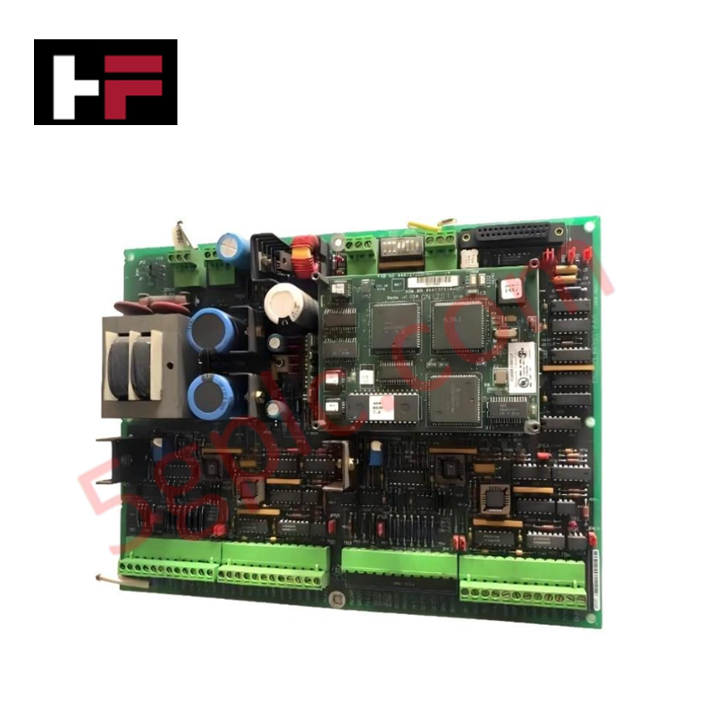
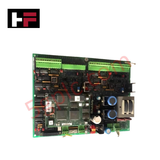
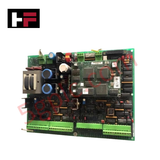
Configured for high-precision rotor feedback processing in Mark V control systems, the General Electric DS200LRPBG1AAA (DS200LRPBG1AAA Resolver Board) provides direct physical/electrical execution of rotary transformer signal digitization and system interface.
Hardware Specifications
| Parameter | Specification |
|---|---|
| Model | DS200LRPBG1AAA |
| Brand | General Electric |
| Origin | United States of America (USA) |
| Input Type | Analog resolver (rotary transformer) |
| Output Type | Digitized position/speed data |
Industrial Control and Drive Systems
The DS200LRPBG1AAA leverages backplane bus communication velocity to transmit digitized rotor dynamics data to host controllers. The board supports firmware flash compatibility, facilitating refined signal processing algorithms for speed and position feedback loops. Through integrated I/O density scaling, the module converts raw analog inputs into deterministic data formats, essential for synchronizing motor control and turbine management functions. The board architecture includes localized signal refinement circuits and dedicated diagnostic LED indicators that map directly to status registers within the drive control network.
Frequently Asked Questions (FAQ)
Q: How does the board interface with the resolver hardware?
A: The board receives raw analog excitation and feedback signals from the rotary transformer (resolver). Internal microprocessors perform the signal conversion and digitization, preparing the data for transmission to the Mark V control system.
Q: What is the primary purpose of the onboard LED indicators?
A: The diagnostic LEDs provide real-time visual status of the board's operational health, allowing field technicians to identify signal loss, conversion errors, or internal hardware faults without requiring external diagnostic tools.
Field Installation Guidelines
- Signal Shielding: Resolver signals are sensitive to electromagnetic interference (EMI). Ensure that shielded twisted-pair cables are used for all resolver-to-board connections and that the shield is grounded at a single, clean instrumentation ground point to minimize crosstalk.
- Connector Integrity: Verify that all cabling connected to the I/O terminals is fully seated. Given the high-frequency nature of resolver signal excitation, any loose connection will result in noise or inaccurate position feedback, potentially causing control instability.
- Mounting: Ensure the board is securely fastened within the Mark V rack. Vibration can induce mechanical stress on the signal conversion components, leading to drift in the digitized position signal.
- Grounding: Verify that the rack chassis provides a low-impedance path to the system ground. This is necessary for the stability of the analog-to-digital conversion circuits and to maintain the integrity of the diagnostic status indicators.
Additional Information
- 100% Genuine Parts: All products are original and authentic, ensuring reliable industrial performance.
- 30-Day Refund Guarantee: Return any in-stock item within 30 days in original, unopened packaging for a full refund (excluding shipping and fees).
- 12-Month Warranty: Covers defects in materials or workmanship; excludes misuse, normal wear, or unauthorized modifications.
- Worldwide Shipping: We ship via USPS, UPS, FedEx, and DHL. Delivery times vary by country and may be subject to customs or import fees.
- Support & Contact: Technical and warranty assistance is available anytime. Contact us here: Contact.
- Purchase Guidance: Check product specifications and compatibility carefully before ordering to ensure proper application.


Tech & Buying Guide

Marshalling Cabinet Preventive Maintenance: Essential Healthiness Checks for PLC, DCS, and ESD Systems
Marshalling cabinets serve as the vital interface between field instrumentation and control room electronics in modern process facilities. Regular preventive maintenance of these cabinets ensures signal integrity across programmable logic controllers (PLCs), distributed control systems (DCS), and emergency shutdown (ESD) networks. System technicians must execute structured inspection protocols to mitigate environmental risks, identify loose wiring, and maintain continuous operational readiness.

Spatial Computing in Industrial Automation: Elevating PLC and DCS Operations with AR and VR
Industry 4.0 integrates digital intelligence into field operations, transforming factory automation landscapes worldwide. Spatial technologies—specifically Augmented Reality (AR) and Virtual Reality (VR)—redefine how engineers interact with industrial control systems. By bridging computer-generated CAD models with real-time operational technology (OT) data, immersive displays enable intuitive monitoring, rapid diagnostics, and safer maintenance across complex processing facilities.

Master Acceptance Testing: Understanding FAT and SAT in Industrial Control Systems
Factory Acceptance Testing (FAT) and Site Acceptance Testing (SAT) serve as critical quality assurance gateways in complex industrial control systems. Both procedures verify that programmable logic controllers (PLCs), distributed control systems (DCS), and associated field devices meet strict functional specifications. However, executing these tests effectively requires clear delineation between off-site staging and final field commissioning.