


Product Details
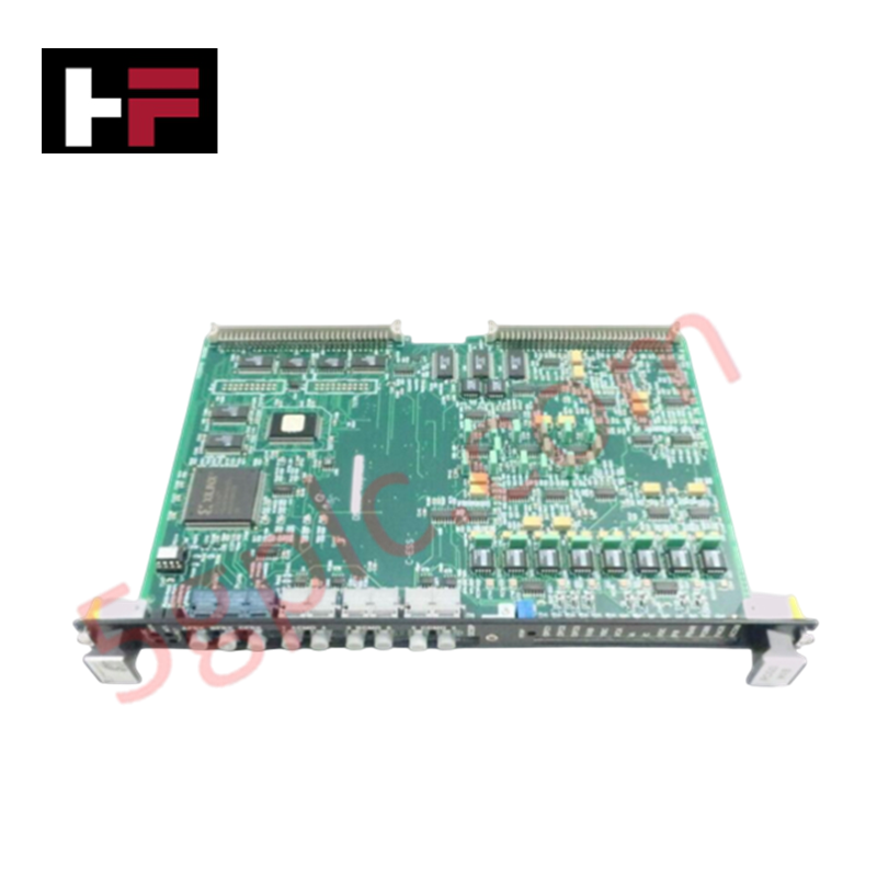
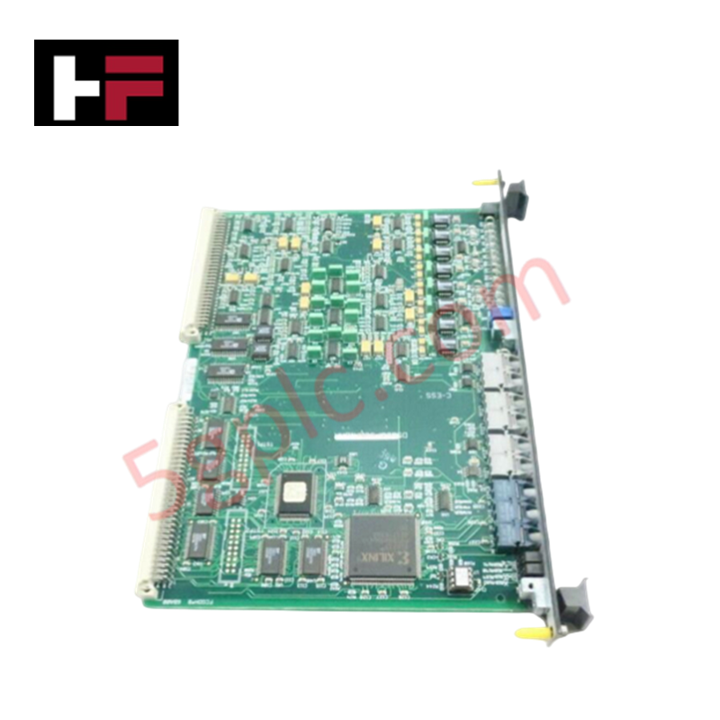
The GE DS200FCGDH1BAA, also cataloged as the DS200FCGDH1 Gating and LCI Control Board, operates as a dedicated hardware component for phase-controlled bridge gating and signal distribution within Mark V Speedtronic turbine control systems.
Hardware Specifications
| Parameter | Specification |
|---|---|
| Model | DS200FCGDH1BAA |
| Brand | General Electric |
| Origin | USA |
| Weight | 0.34 kg (12 ounces) |
| Core Components | Xilinx FPGA, DSPC interface, 2 rear male connectors |
Industrial Control & Firmware Compatibility
The DS200FCGDH1BAA module is engineered to integrate into VME backplane architectures, serving as a gateway for phase-controlled non-reversing bridge systems. Computational logic is managed via an onboard Xilinx FPGA, which interprets signals relayed from the DSPC board. Firmware flash compatibility is intrinsically linked to the FPGA logic configuration; therefore, hardware replacement must ensure parity with existing system-level firmware versions to maintain deterministic timing in gating pulses. I/O density scaling is managed through high-speed backplane bus communication, requiring precise seating within the drive rack to ensure electrical continuity across the rear horizontal male connectors.
Frequently Asked Questions
Q: Can the DS200FCGDH1BAA be hot-swapped while the drive is energized?
A: No. The board must not be removed or inserted while the system is under power. The unit contains sensitive FPGA logic and VME backplane pins that may be damaged by transient voltages or improper seating sequences during hot-swapping.
Q: What is the purpose of the LED indicators on the front faceplate?
A: The LEDs located on the lower surface of the front faceplate provide visual diagnostic feedback regarding the operational state of the gating signals and card communication status. Refer to system-specific status tables for interpretation of indicator patterns during active operation.
Field Installation Guidelines
- Mechanical Mounting: Ensure the faceplate clip components are fully engaged after insertion. The clips provide necessary structural retention to prevent the board from backing out of the VME slot due to mechanical vibration within the turbine cabinet.
- Connector Alignment: Align the rear male connectors carefully with the backplane receptors. Forceful insertion can bend or damage the pins, leading to intermittent signal transmission or short circuits.
- ESD Prevention: Use anti-static protection when handling the PCB. As the board contains field-programmable gate arrays, it is susceptible to damage from electrostatic discharge during manual handling.
- Signal Grounding: Ensure the faceplate is firmly secured to the cabinet chassis to maintain a consistent chassis ground reference, which is required to minimize electromagnetic interference on the gate signal paths.
Additional Information
- 100% Genuine Parts: All products are original and authentic, ensuring reliable industrial performance.
- 30-Day Refund Guarantee: Return any in-stock item within 30 days in original, unopened packaging for a full refund (excluding shipping and fees).
- 12-Month Warranty: Covers defects in materials or workmanship; excludes misuse, normal wear, or unauthorized modifications.
- Worldwide Shipping: We ship via USPS, UPS, FedEx, and DHL. Delivery times vary by country and may be subject to customs or import fees.
- Support & Contact: Technical and warranty assistance is available anytime. Contact us here: Contact.
- Purchase Guidance: Check product specifications and compatibility carefully before ordering to ensure proper application.


Tech & Buying Guide

Redundant Automation Systems: Ensuring Continuous Uptime in Critical Control Infrastructure
System reliability directly determines operational profitability across high stakes process industries. Modern industrial automation platforms must eliminate single points of failure to prevent catastrophic shutdowns. Deploying fault tolerant architecture safeguards complex facilities against unexpected hardware glitches, network disruptions, and maintenance outages.

Understanding Types of Noise in Electronic Circuits and Control Systems
Signal integrity directly determines measurement accuracy and loop stability across industrial automation environments. Electronic noise introduces unwanted stochastic interference into analog loops, sensor feedback lines, and digital fieldbus networks. Understanding how intrinsic electronic noise and external electromagnetic interference manifest allows control engineers to optimize signal conditioning and shield sensitive instrumentation effectively.

Why 24V DC Power Supplies Standardize Modern Industrial Automation
Industrial control cabinets worldwide rely on 24V DC as the universal power standard for field instrumentation, sensors, and controllers. Walk into any manufacturing plant, and you will find PLCs, human-machine interfaces (HMIs), and smart actuators running on extra-low voltage DC. Standardizing on 24V DC enhances operational safety, lowers cabinet footprint, and maintains steady control performance across factory networks.