


Product Details
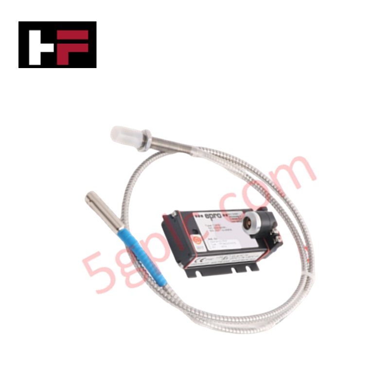
Configured for high-frequency displacement measurement in turbomachinery monitoring systems, the Emerson PR6423/014-010 (PR6423/014-010) transducer paired with the CON021 signal converter provides direct physical/electrical execution.
Hardware Specifications
| Parameter | Specification |
|---|---|
| Model | PR6423/014-010 + CON021 |
| Brand | Emerson |
| Origin | USA |
| Weight | 0.18 kg |
| Dimensions | 18 cm x 18 cm x 4 cm |
| Operating Temp | Industrial grade |
| Power Consumption | Nominal excitation required |
| Performance | Radial/axial dynamic displacement and speed measurement |
Gap Voltage Validation (-10 VDC targets)
The system utilizes an oscillator circuit to drive the transducer probe, creating an electromagnetic field for displacement detection. To ensure accurate linearization, the system necessitates precise gap voltage validation during commissioning. The converter centers its output characteristic around a nominal target of -10 VDC, representing the mid-point of the physical measurement gap. Maintenance of this -10 VDC baseline is mandatory for accurate signal tracking; significant deviations indicate mechanical misalignment, transducer saturation, or degradation of the conductive target surface.
Frequently Asked Questions
Q: What is the primary function of the CON021 converter in this loop?
A: The CON021 functions as an oscillator-demodulator, converting the high-frequency probe impedance changes into a proportional analog signal for monitoring instrumentation.
Q: Is field-splicing of the probe cable permissible?
A: Field-splicing is prohibited. The probe and cable are a matched impedance assembly; any physical modification to the cable length or integrity will introduce signal errors and calibration drift.
Field Installation Guidelines
- Mount the transducer in a rigid, vibration-isolated bracket to minimize extraneous mechanical noise and prevent housing fatigue.
- Ensure the measurement target surface is clean and free of non-conductive coatings to maintain the required electrical conductivity.
- Establish the nominal air gap using a non-metallic feeler gauge to prevent contact damage to the sensor tip during startup.
- Route signal cabling through grounded metallic conduit, keeping lines physically separated from high-current AC power lines to mitigate electromagnetic interference.
- Terminate the signal shield at the monitoring system (DCS/TSI) rack only to prevent ground-loop current injection into the converter circuit.
Additional Information
- 100% Genuine Parts: All products are original and authentic, ensuring reliable industrial performance.
- 30-Day Refund Guarantee: Return any in-stock item within 30 days in original, unopened packaging for a full refund (excluding shipping and fees).
- 12-Month Warranty: Covers defects in materials or workmanship; excludes misuse, normal wear, or unauthorized modifications.
- Worldwide Shipping: We ship via USPS, UPS, FedEx, and DHL. Delivery times vary by country and may be subject to customs or import fees.
- Support & Contact: Technical and warranty assistance is available anytime. Contact us here: Contact.
- Purchase Guidance: Check product specifications and compatibility carefully before ordering to ensure proper application.


Tech & Buying Guide

Understanding Dry Contacts in PLC Wiring: An Industrial Automation Guide
Mastering contact switching principles is essential for reliable control panels. Field devices and PLCs interface through dry or wet contacts. This technical guide examines the mechanics of dry contacts, explores their wiring architectures, and evaluates their key advantages in industrial automation.

Ultimate Commissioning Checklist for Industrial Automation Systems: An Engineering Guide
Commissioning is the most decisive phase of an industrial automation project, transforming control hardware and software into an operational facility. Thorough testing prevents costly startup delays and builds customer confidence. This guide covers essential checklists, electrical standards, and best practices.

Redundant Automation Systems: Core Architecture, Business Value, and Technical Advantages
Unplanned downtime poses a major financial threat to process manufacturing. To prevent costly interruptions, engineers deploy redundant PLC and DCS architectures that ensure continuous operation when hardware fails. This technical guide explores redundancy principles, critical system nodes, and real-world scenarios.