


Product Details
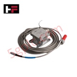
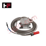
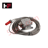
Configured for non-contact displacement measurement in rotating machinery monitoring networks, the Emerson epro PR6424/013-140 CON021 (PR6424/013-140) Eddy Current Proximitor System provides direct physical execution of dynamic and static signal conversion for axial and radial shaft monitoring.
Hardware Specifications
| Parameter | Specification |
|---|---|
| Model | PR6424/013-140 CON021 |
| Brand | Emerson epro |
| Origin | Not Specified |
| Weight | 0.32 kg (Combined system) |
| Dimensions | M18x1.5 (Sensor) / DIN-rail mount (Converter) |
| Operating Temp | -30 deg C to +100 deg C (Converter) |
| Power Consumption | 23 VDC to 32 VDC |
Mechanical Monitoring and TSI Integration
The PR6424/013-140 utilizes electromagnetic induction to measure the distance relative to a rotating metallic shaft. Achieving accurate rotor dynamics data necessitates precise eddy-current probe scaling to ensure the output voltage reflects true mechanical displacement at a sensitivity of 4 V/mm. During installation, users must verify gap voltage validation, maintaining targets near -10 VDC to ensure operation within the linear range of the probe's characteristic curve. Furthermore, to preserve high-fidelity waveform capture, the system requires effective cross-talk suppression by ensuring proper routing and shielding of the 10 m interconnecting coaxial cables, preventing common-mode noise from influencing the perceived shaft position or vibration frequency.
Frequently Asked Questions
Q: Can the 10 m cable length of the PR6424/013-140 be field-shortened?
A: No. The system is factory-calibrated as a complete signal chain. Altering the coaxial cable length changes the system impedance and resonant frequency, which introduces significant measurement errors.
Q: Is the system sensitive to power supply fluctuations?
A: The CON021 operates within a -23 VDC to -32 VDC supply range. Voltage levels outside this window may cause signal drift or non-linear output response, impacting the reliability of the protective trip logic in connected monitoring systems.
Field Installation Guidelines
- Probe Gap Setting: Establish the initial gap between the probe tip and the shaft surface using a calibrated feeler gauge. Target the mid-point of the linear measurement range to allow for shaft movement in both directions.
- Mounting Integrity: Secure the probe within a rigid, vibration-isolated bracket. Any flexure in the mounting assembly will be perceived by the sensor as shaft vibration, resulting in erroneous condition monitoring data.
- Cable Routing: Route coaxial cables away from high-current power lines and variable frequency drive (VFD) outputs. Use shielded conduits to prevent electromagnetic interference (EMI) from inducing noise into the high-impedance signal path.
- Connector Care: Inspect the Lemo-plug connections for contaminants or moisture. Ensure the interface is clean and dry to prevent leakage paths that cause signal attenuation and gap voltage drift.
Additional Information
- 100% Genuine Parts: All products are original and authentic, ensuring reliable industrial performance.
- 30-Day Refund Guarantee: Return any in-stock item within 30 days in original, unopened packaging for a full refund (excluding shipping and fees).
- 12-Month Warranty: Covers defects in materials or workmanship; excludes misuse, normal wear, or unauthorized modifications.
- Worldwide Shipping: We ship via USPS, UPS, FedEx, and DHL. Delivery times vary by country and may be subject to customs or import fees.
- Support & Contact: Technical and warranty assistance is available anytime. Contact us here: Contact.
- Purchase Guidance: Check product specifications and compatibility carefully before ordering to ensure proper application.


Tech & Buying Guide

Understanding Dry Contacts in PLC Wiring: An Industrial Automation Guide
Mastering contact switching principles is essential for reliable control panels. Field devices and PLCs interface through dry or wet contacts. This technical guide examines the mechanics of dry contacts, explores their wiring architectures, and evaluates their key advantages in industrial automation.

Ultimate Commissioning Checklist for Industrial Automation Systems: An Engineering Guide
Commissioning is the most decisive phase of an industrial automation project, transforming control hardware and software into an operational facility. Thorough testing prevents costly startup delays and builds customer confidence. This guide covers essential checklists, electrical standards, and best practices.

Redundant Automation Systems: Core Architecture, Business Value, and Technical Advantages
Unplanned downtime poses a major financial threat to process manufacturing. To prevent costly interruptions, engineers deploy redundant PLC and DCS architectures that ensure continuous operation when hardware fails. This technical guide explores redundancy principles, critical system nodes, and real-world scenarios.