


Product Details
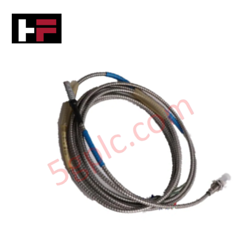
Configured for non-contact measurement of radial and axial shaft displacement, position, and eccentricity, the Emerson Epro PR6423/10R-111 (PR6423/10R-111 Eddy Current Sensor) provides direct physical signal execution. This transducer detects impedance variations induced by target surfaces to supply high-resolution data streams for turbomachinery monitoring and diagnostic platforms.
Hardware Specifications
| Parameter | Specification |
|---|---|
| Model | PR6423/10R-111 |
| Brand | Emerson (Epro) |
| Origin | Subject to certificate of origin |
| Weight | Not specified |
| Dimensions | 8 mm Sensor diameter |
| Operating Temp | -35 deg C to +200 deg C |
| Power Consumption | Dependent on interface converter |
| Measurement Range | 2 mm |
| Scale Factor | 8 V/mm (203.2 mV/mil) |
| Protection Class | IP66 |
Eddy-Current Probe Scaling and Rotor Dynamics
The measurement accuracy of the Emerson Epro PR6423/10R-111 depends on precise scaling relative to the AISI 4140 ferromagnetic shaft target. To maintain linearity within the specified range, the initial air gap must be set at 0.5 mm, corresponding to the factory-calibrated nominal output voltage. Rotor dynamics analysis requires that the probe be mounted in a orientation perpendicular to the shaft centerline, with sufficient cross-talk suppression provided by maintaining minimum spatial separation between adjacent sensors to avoid signal interference from overlapping oscillation fields.
Frequently Asked Questions
Q: Can the sensor be operated in environments exceeding 200 deg C?
A: No, operating the sensor above 200 deg C will cause irreversible degradation of the internal coil potting and PEEK tip material, leading to signal loss and permanent calibration drift.
Q: Is the sensor assembly compatible with standard field-wiring of CON021 converters?
A: Yes, the transducer is designed for seamless integration with the CON021 signal converter. Ensure that the signal path impedance is maintained to prevent attenuation of the 30 kHz carrier signal.
Q: What is the impact of using non-ferromagnetic targets?
A: The transducer is factory-calibrated for ferromagnetic steel targets. Using non-ferromagnetic materials will cause significant non-linearity and a drastic reduction in the Incremental Scale Factor (ISF).
Field Installation Guidelines
- Mounting: Ensure the sensor is installed using a rigid, vibration-resistant bracket. Use a locking nut to secure the position after setting the 0.5 mm air gap.
- Grounding: Route the cable through a grounded metallic conduit to prevent EMI. Connect the cable shield to a single dedicated instrument ground point to eliminate ground loops.
- Wiring: Observe temperature limits for the cable and connector (-35 deg C to +150 deg C). Ensure the connection point is isolated from excessive heat sources.
- Target Geometry: Verify that the shaft surface is smooth, clean, and free of scratches or electrical run-out, which can introduce artificial noise into the dynamic signal.
Additional Information
- 100% Genuine Parts: All products are original and authentic, ensuring reliable industrial performance.
- 30-Day Refund Guarantee: Return any in-stock item within 30 days in original, unopened packaging for a full refund (excluding shipping and fees).
- 12-Month Warranty: Covers defects in materials or workmanship; excludes misuse, normal wear, or unauthorized modifications.
- Worldwide Shipping: We ship via USPS, UPS, FedEx, and DHL. Delivery times vary by country and may be subject to customs or import fees.
- Support & Contact: Technical and warranty assistance is available anytime. Contact us here: Contact.
- Purchase Guidance: Check product specifications and compatibility carefully before ordering to ensure proper application.


Tech & Buying Guide

Understanding Dry Contacts in PLC Wiring: An Industrial Automation Guide
Mastering contact switching principles is essential for reliable control panels. Field devices and PLCs interface through dry or wet contacts. This technical guide examines the mechanics of dry contacts, explores their wiring architectures, and evaluates their key advantages in industrial automation.

Ultimate Commissioning Checklist for Industrial Automation Systems: An Engineering Guide
Commissioning is the most decisive phase of an industrial automation project, transforming control hardware and software into an operational facility. Thorough testing prevents costly startup delays and builds customer confidence. This guide covers essential checklists, electrical standards, and best practices.

Redundant Automation Systems: Core Architecture, Business Value, and Technical Advantages
Unplanned downtime poses a major financial threat to process manufacturing. To prevent costly interruptions, engineers deploy redundant PLC and DCS architectures that ensure continuous operation when hardware fails. This technical guide explores redundancy principles, critical system nodes, and real-world scenarios.