


Product Details
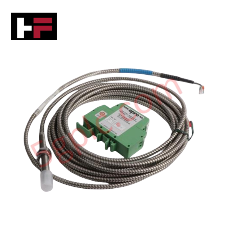
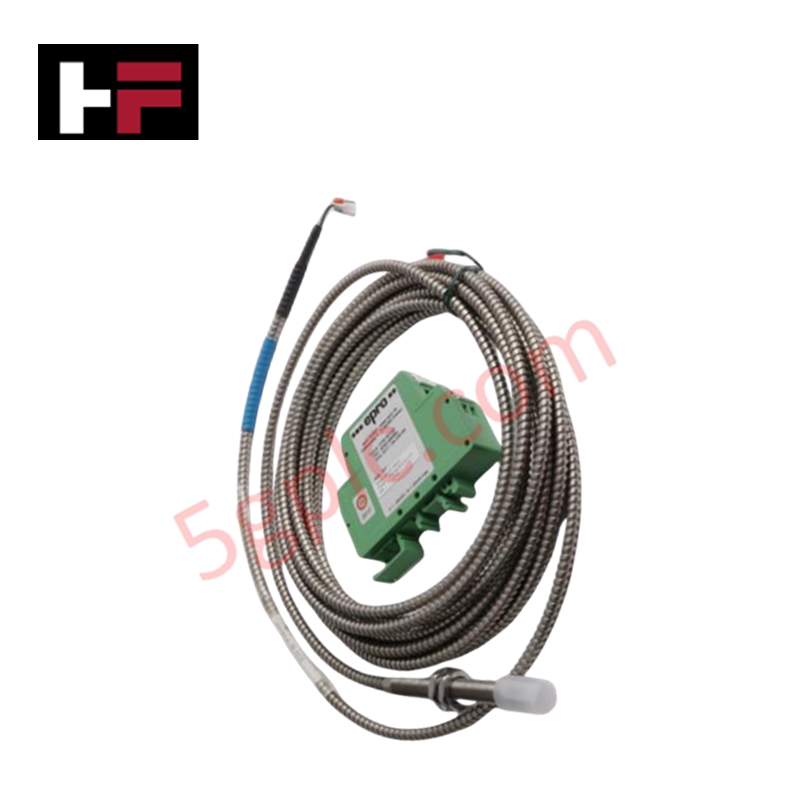
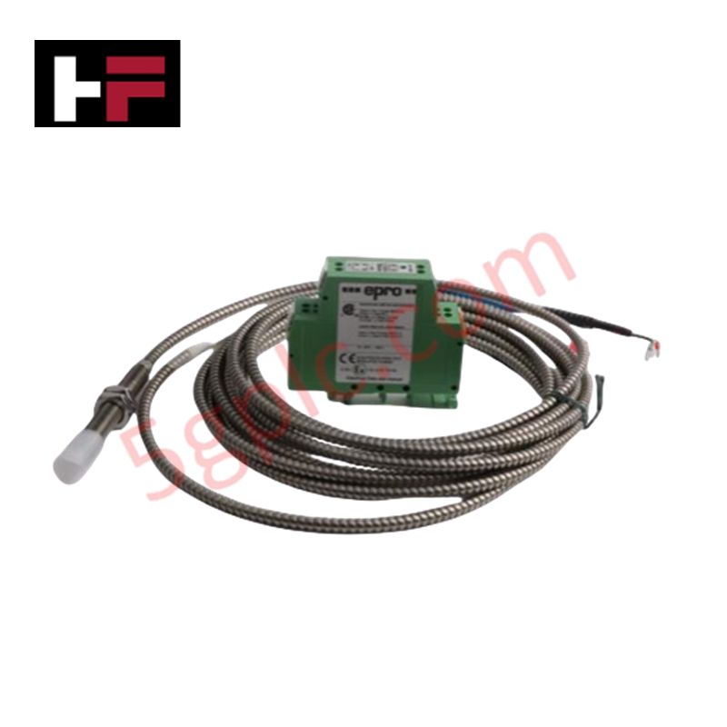
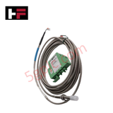
Configured for high-frequency shaft displacement acquisition in rotating machinery, the Emerson Epro CON041+PR6423/002-031 (PR6423/002-031) Eddy Current Sensor system provides direct physical execution of dynamic and static signal conversion for axial and radial shaft monitoring.
Hardware Specifications
| Parameter | Specification |
|---|---|
| Model | CON041+PR6423/002-031 |
| Brand | Emerson Epro |
| Weight | ~0.25 kg (System total) |
| Dimensions | M8 (Probe) / DIN rail module (Converter) |
| Operating Temp | -30 deg C to +100 deg C (Converter) |
| Power Consumption | -23 VDC to -32 VDC |
Mechanical Monitoring and TSI Integration
The system utilizes eddy-current induction to measure the clearance between the probe tip and a metallic rotor. Successful rotor dynamics analysis is dependent on accurate eddy-current probe scaling, ensuring the transducer voltage output remains linearly proportional to shaft displacement. During initial setup, users must perform gap voltage validation, targeting a -10 VDC center point to ensure the signal remains within the linear dynamic range of the probe. Furthermore, to maintain high-fidelity waveform capture, the system utilizes effective cross-talk suppression by ensuring that the high-frequency coaxial cables are routed away from electromagnetic noise sources, preventing interference with the monitoring of shaft eccentricity and orbital vibration.
Frequently Asked Questions
Q: Can the integrated coaxial cable of the PR6423 probe be modified or spliced?
A: No. The system is factory-calibrated as a matched set including the cable impedance. Modifying or splicing the cable will alter the resonant frequency and system sensitivity, leading to significant measurement errors in shaft position data.
Q: Is the CON041 converter module capable of hot-swapping?
A: No. Disconnect the supply voltage (-23 VDC to -32 VDC) before removing or installing the module on the DIN rail. Hot-swapping may induce voltage transients that can damage the internal demodulation circuitry.
Field Installation Guidelines
- Probe Mounting: Install the probe in a rigid, vibration-isolated bracket to ensure measured displacement is relative to the shaft and not the machine casing.
- Gap Adjustment: Use a calibrated feeler gauge to establish the nominal air gap at the center of the measurement span. Verify the gap allows for full shaft thermal expansion and movement without physical contact.
- Grounding: Terminate the converter housing and cable shields to a low-impedance instrument ground. Proper grounding is necessary to mitigate common-mode noise and prevent drift in the gap voltage reference.
- Environment: Route signal cables through dedicated conduits, separated from high-voltage power lines and VFD output cabling, to prevent electromagnetic interference.
Additional Information
- 100% Genuine Parts: All products are original and authentic, ensuring reliable industrial performance.
- 30-Day Refund Guarantee: Return any in-stock item within 30 days in original, unopened packaging for a full refund (excluding shipping and fees).
- 12-Month Warranty: Covers defects in materials or workmanship; excludes misuse, normal wear, or unauthorized modifications.
- Worldwide Shipping: We ship via USPS, UPS, FedEx, and DHL. Delivery times vary by country and may be subject to customs or import fees.
- Support & Contact: Technical and warranty assistance is available anytime. Contact us here: Contact.
- Purchase Guidance: Check product specifications and compatibility carefully before ordering to ensure proper application.


Tech & Buying Guide

Understanding Dry Contacts in PLC Wiring: An Industrial Automation Guide
Mastering contact switching principles is essential for reliable control panels. Field devices and PLCs interface through dry or wet contacts. This technical guide examines the mechanics of dry contacts, explores their wiring architectures, and evaluates their key advantages in industrial automation.

Ultimate Commissioning Checklist for Industrial Automation Systems: An Engineering Guide
Commissioning is the most decisive phase of an industrial automation project, transforming control hardware and software into an operational facility. Thorough testing prevents costly startup delays and builds customer confidence. This guide covers essential checklists, electrical standards, and best practices.

Redundant Automation Systems: Core Architecture, Business Value, and Technical Advantages
Unplanned downtime poses a major financial threat to process manufacturing. To prevent costly interruptions, engineers deploy redundant PLC and DCS architectures that ensure continuous operation when hardware fails. This technical guide explores redundancy principles, critical system nodes, and real-world scenarios.