


Product Details
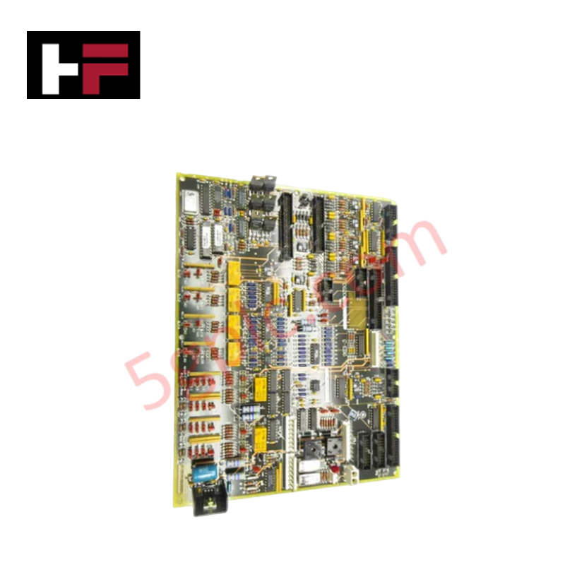
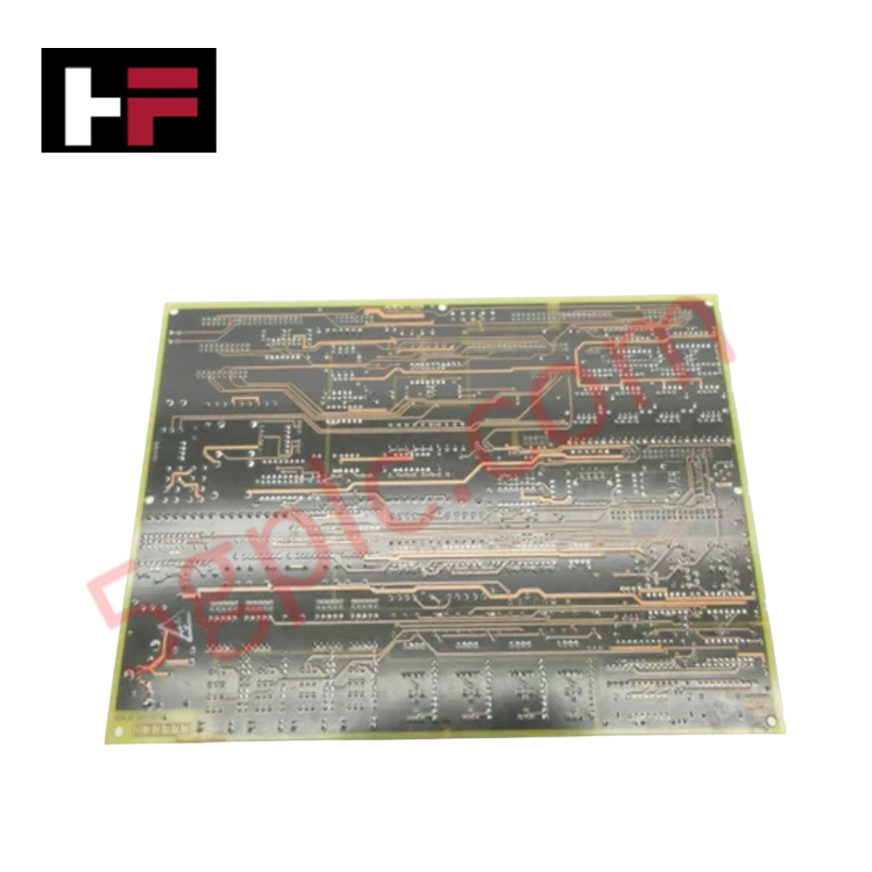
Configured for signal routing and circuit switching within Mark V gas turbine control systems, the GE DS200TCQCG1BJF (DS200TCQC RST Overflow Board) provides direct physical execution of interconnectivity between turbine management components.
Hardware Specifications
| Parameter | Specification |
|---|---|
| Model | DS200TCQCG1BJF |
| Brand | General Electric |
| Core Components | 24 jumpers, 3x 40-pin connectors (JFF, JE, 6PL), 3x 34-pin connectors (JFF, 1PL, JA), 1x 16-pin connector (JC) |
Industrial Control & Firmware Compatibility
The DS200TCQCG1BJF acts as an overflow and distribution interface for the Mark V RST system. Backplane bus communication velocity is managed through high-density ribbon cables, ensuring deterministic signal propagation between the overflow board and host turbine controllers. This module does not utilize onboard firmware; therefore, firmware flash compatibility requirements are not applicable to the hardware itself. System configuration relies on the 24 onboard jumpers, which must be set according to the site-specific turbine control logic to correctly route signals between the 40-pin and 34-pin interface ports. I/O density is defined by the fixed connector layout, facilitating modular expansion of the turbine control suite.
Frequently Asked Questions
Q: Do the relays on this board require routine maintenance?
A: No. The relays are soldered directly to the board via leads and are designed for maintenance-free operation. If relay failure occurs, the entire PCB module must be replaced as a single unit.
Q: What is the purpose of the 24 onboard jumpers?
A: The jumpers serve to configure the signal routing paths for the board. They must be configured in accordance with the specific turbine control cabinet wiring diagrams to ensure correct relay state transition and signal mapping to the connected ribbon cables.
Field Installation Guidelines
- Ribbon Cable Management: The board utilizes multiple ribbon cables for data transmission. Ensure these cables are routed away from high-current power lines to prevent induced electromagnetic interference.
- Connector Integrity: The 40-pin and 34-pin connectors are friction-fit ribbon cable headers. Inspect the pins for oxidation or bending before mating. Ensure cables are fully seated to prevent intermittent signal continuity.
- Grounding: Ensure the board is properly mounted to the cabinet chassis. Proper grounding is required to ensure the reference potential of the signal relays is maintained across the RST control loop.
- Static Awareness: As the board contains sensitive integrated logic and relay switching arrays, use standard ESD-safe practices when handling to prevent damage to the PCB substrate and soldered components.
Additional Information
- 100% Genuine Parts: All products are original and authentic, ensuring reliable industrial performance.
- 30-Day Refund Guarantee: Return any in-stock item within 30 days in original, unopened packaging for a full refund (excluding shipping and fees).
- 12-Month Warranty: Covers defects in materials or workmanship; excludes misuse, normal wear, or unauthorized modifications.
- Worldwide Shipping: We ship via USPS, UPS, FedEx, and DHL. Delivery times vary by country and may be subject to customs or import fees.
- Support & Contact: Technical and warranty assistance is available anytime. Contact us here: Contact.
- Purchase Guidance: Check product specifications and compatibility carefully before ordering to ensure proper application.


Tech & Buying Guide

Redundant Automation Systems: Ensuring Continuous Uptime in Critical Control Infrastructure
System reliability directly determines operational profitability across high stakes process industries. Modern industrial automation platforms must eliminate single points of failure to prevent catastrophic shutdowns. Deploying fault tolerant architecture safeguards complex facilities against unexpected hardware glitches, network disruptions, and maintenance outages.

Understanding Types of Noise in Electronic Circuits and Control Systems
Signal integrity directly determines measurement accuracy and loop stability across industrial automation environments. Electronic noise introduces unwanted stochastic interference into analog loops, sensor feedback lines, and digital fieldbus networks. Understanding how intrinsic electronic noise and external electromagnetic interference manifest allows control engineers to optimize signal conditioning and shield sensitive instrumentation effectively.

Why 24V DC Power Supplies Standardize Modern Industrial Automation
Industrial control cabinets worldwide rely on 24V DC as the universal power standard for field instrumentation, sensors, and controllers. Walk into any manufacturing plant, and you will find PLCs, human-machine interfaces (HMIs), and smart actuators running on extra-low voltage DC. Standardizing on 24V DC enhances operational safety, lowers cabinet footprint, and maintains steady control performance across factory networks.