


Product Details
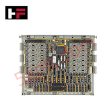
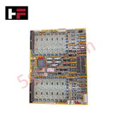
Configured for digital signal interfacing in Mark V Speedtronic systems, the GE DS200TCDAH1BHD (DS200TCDAH1 Digital I/O Board) provides direct physical electrical conditioning and status monitoring for turbine control inputs and outputs.
Hardware Specifications
| Parameter | Specification |
|---|---|
| Model | DS200TCDAH1BHD |
| Brand | General Electric |
| Core Components | 8 jumpers, 1 single LED, 1 block of 10 LEDs, 2 3-pin connectors, 2 50-pin connectors |
Industrial Control & Firmware Compatibility
The DS200TCDAH1BHD operates as a high-density digital interface, managing contact input and output signals via specialized daisy-chained IONET connectors. System integration requires strict adherence to backplane bus communication velocity parameters to ensure deterministic signal processing across the Mark V controller. Users must manage I/O density scaling through the 8 onboard jumpers (JP1–JP8), which define the electrical behavior and signal addressing of the module. As this board does not support field-programmable firmware updates, site-specific operational logic is established entirely through physical jumper positioning; ensure these are mapped to the site-specific installation manual before initialization.
Frequently Asked Questions
Q: Are the jumper settings on the replacement board automatically configured?
A: No. Factory default settings are provided; however, these may not match specific site requirements. Technicians must document the jumper positions of the legacy board and replicate the configuration on the replacement board (e.g., verifying pin coverage on JP1–JP8) prior to installation.
Q: What is the function of the onboard LED array?
A: The single LED and the block of 10 LEDs provide status monitoring for the board's internal logic and active signal state. A failure of these LEDs to illuminate during system power-up may indicate a board-level power distribution fault or a failure in the J1 TCPS power input path.
Field Installation Guidelines
- Connector Integrity: The board utilizes multiple high-pin-count connectors (JX1, JX2, JQ, JR, JO1, JO2). Ensure these are seated square to the headers to prevent pin deformation. Avoid excessive force, as these connectors are critical for IONET and contact signal reliability.
- Grounding and Shielding: Ensure that signal cabling for contact inputs (JQ/JR) and outputs (JO1/JO2) is properly shielded to prevent ground loop interference. The board relies on a common reference; improper bonding can induce noise in the digital I/O processing path.
- Conformal Coating Care: This board is finished with a conformal coating to protect against environmental degradation. Handle by the edges only to avoid scratching the coating or damaging surface-mounted components, which could compromise the board's environmental rating.
- Jumper Verification: Prior to energizing the system, verify that any jumper marked for factory-only use remains in its original position. Altering these specific jumpers may result in undefined board states or control logic failure.
Additional Information
- 100% Genuine Parts: All products are original and authentic, ensuring reliable industrial performance.
- 30-Day Refund Guarantee: Return any in-stock item within 30 days in original, unopened packaging for a full refund (excluding shipping and fees).
- 12-Month Warranty: Covers defects in materials or workmanship; excludes misuse, normal wear, or unauthorized modifications.
- Worldwide Shipping: We ship via USPS, UPS, FedEx, and DHL. Delivery times vary by country and may be subject to customs or import fees.
- Support & Contact: Technical and warranty assistance is available anytime. Contact us here: Contact.
- Purchase Guidance: Check product specifications and compatibility carefully before ordering to ensure proper application.


Tech & Buying Guide

Redundant Automation Systems: Ensuring Continuous Uptime in Critical Control Infrastructure
System reliability directly determines operational profitability across high stakes process industries. Modern industrial automation platforms must eliminate single points of failure to prevent catastrophic shutdowns. Deploying fault tolerant architecture safeguards complex facilities against unexpected hardware glitches, network disruptions, and maintenance outages.

Understanding Types of Noise in Electronic Circuits and Control Systems
Signal integrity directly determines measurement accuracy and loop stability across industrial automation environments. Electronic noise introduces unwanted stochastic interference into analog loops, sensor feedback lines, and digital fieldbus networks. Understanding how intrinsic electronic noise and external electromagnetic interference manifest allows control engineers to optimize signal conditioning and shield sensitive instrumentation effectively.

Why 24V DC Power Supplies Standardize Modern Industrial Automation
Industrial control cabinets worldwide rely on 24V DC as the universal power standard for field instrumentation, sensors, and controllers. Walk into any manufacturing plant, and you will find PLCs, human-machine interfaces (HMIs), and smart actuators running on extra-low voltage DC. Standardizing on 24V DC enhances operational safety, lowers cabinet footprint, and maintains steady control performance across factory networks.