


Product Details
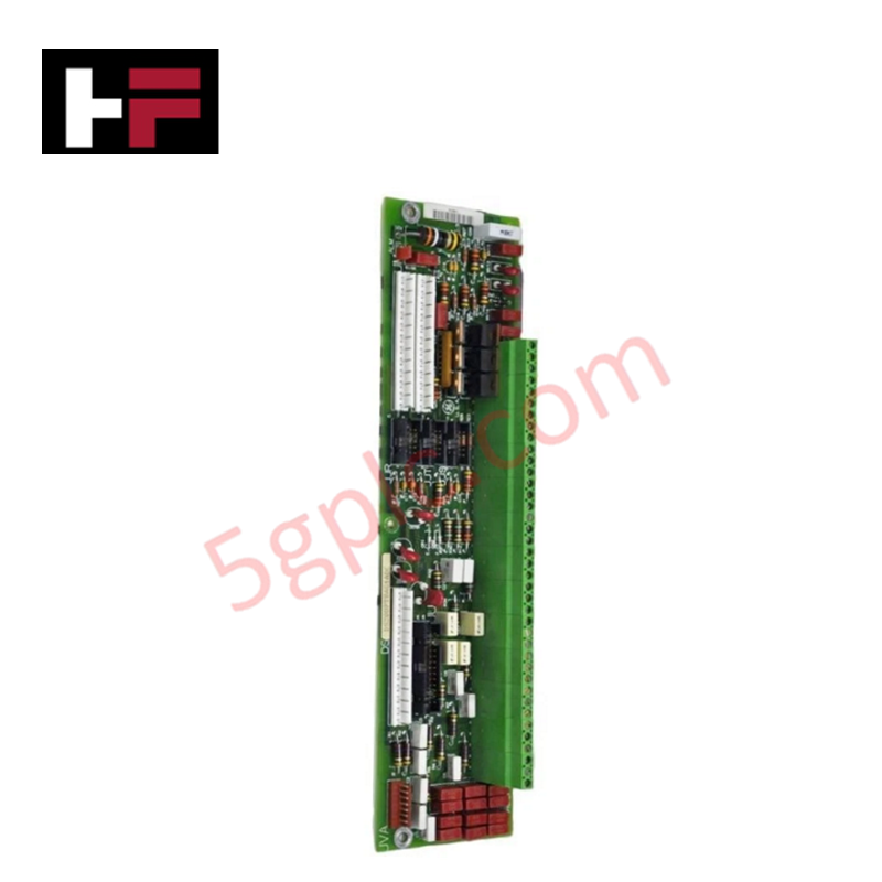
Configured for field signal interfacing in Mark V turbine control systems, the GE DS200PTBAG1AEC (DS200PTBAG1 Termination Board) provides direct physical electrical termination for field wiring and inter-component signal routing.
Hardware Specifications
| Parameter | Specification |
|---|---|
| Model | DS200PTBAG1AEC |
| Brand | General Electric |
| Origin | Not specified |
| Weight | 0.6 kg |
| Dimensions | 29.2 cm x 7.6 cm x 2.5 cm |
| Operating Temp | -40 deg C to +85 deg C |
| Power Consumption | Not specified |
| Core Components | 2 terminal blocks (72 terminals each), 3 10-pin connectors, 6 signal terminal posts |
Industrial Control & Firmware Compatibility
The DS200PTBAG1AEC facilitates signal distribution within the Mark V control architecture, managing backplane bus communication velocity indirectly through organized field-to-controller signal mapping. As a passive termination interface, the board does not contain firmware-dependent logic; therefore, it does not require firmware flash compatibility. However, consistent I/O density scaling relies on precise wire mapping to the 72-terminal blocks. Ensure all connections remain deterministic by verifying the continuity of the three 10-pin inter-component connectors, as signal latency can be introduced by oxidized contacts or high-resistance mechanical terminations in the field wiring path.
Frequently Asked Questions
Q: Does this termination board support hot-swapping?
A: The board is not designed for hot-swapping. Before maintenance or replacement, all field wiring and inter-component connections must be de-energized to prevent short circuits during the removal of signal wires from the terminal blocks.
Q: Are the 10-pin connectors interchangeable between ports?
A: While the connectors utilize the same 10-pin physical interface, they are application-specific based on the Mark V system configuration. Always tag and document the specific cable location (e.g., J1, J2, J3) prior to disconnection to ensure correct signal routing upon re-installation.
Field Installation Guidelines
- Physical Mounting: Utilize the designated mounting hole to secure the board to the control panel chassis. Ensure the mounting surface is clean and conductive if the board design requires chassis grounding for EMI shielding.
- Wiring Practices: Terminate field signal wires into the 72-terminal blocks using appropriate torque settings to prevent loosening under thermal cycling. Use strain relief for all incoming field cables to avoid mechanical stress on the terminal blocks or the PCB itself.
- Signal Shielding: Ground cable shields at the designated terminal posts provided on the board. Proper grounding of signal shields is required to suppress high-frequency noise that can inject errors into the Mark V control processors.
- Visual Inspection: Perform periodic inspection of the terminal posts and pin headers for signs of oxidation or environmental corrosion, particularly in high-humidity or industrial atmospheres, to maintain optimal signal conductivity.
Additional Information
- 100% Genuine Parts: All products are original and authentic, ensuring reliable industrial performance.
- 30-Day Refund Guarantee: Return any in-stock item within 30 days in original, unopened packaging for a full refund (excluding shipping and fees).
- 12-Month Warranty: Covers defects in materials or workmanship; excludes misuse, normal wear, or unauthorized modifications.
- Worldwide Shipping: We ship via USPS, UPS, FedEx, and DHL. Delivery times vary by country and may be subject to customs or import fees.
- Support & Contact: Technical and warranty assistance is available anytime. Contact us here: Contact.
- Purchase Guidance: Check product specifications and compatibility carefully before ordering to ensure proper application.


Tech & Buying Guide

Understanding Dry Contacts in PLC Wiring: An Industrial Automation Guide
Mastering contact switching principles is essential for reliable control panels. Field devices and PLCs interface through dry or wet contacts. This technical guide examines the mechanics of dry contacts, explores their wiring architectures, and evaluates their key advantages in industrial automation.

Ultimate Commissioning Checklist for Industrial Automation Systems: An Engineering Guide
Commissioning is the most decisive phase of an industrial automation project, transforming control hardware and software into an operational facility. Thorough testing prevents costly startup delays and builds customer confidence. This guide covers essential checklists, electrical standards, and best practices.

Redundant Automation Systems: Core Architecture, Business Value, and Technical Advantages
Unplanned downtime poses a major financial threat to process manufacturing. To prevent costly interruptions, engineers deploy redundant PLC and DCS architectures that ensure continuous operation when hardware fails. This technical guide explores redundancy principles, critical system nodes, and real-world scenarios.