


Product Details
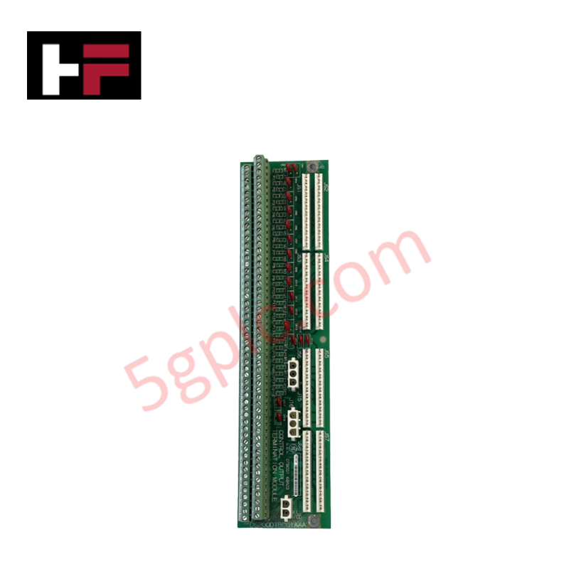
The GE DS200DTBCG1AAA, also cataloged as the DS200DTBCG1 Contact Output Termination Module, operates as a dedicated hardware component for relay signal distribution and contact output termination within Mark V turbine control systems.
Hardware Specifications
| Parameter | Specification |
|---|---|
| Model | DS200DTBCG1AAA |
| Brand | General Electric |
| Core Components | 2 terminal blocks (110 pins each), 10 jumpers |
Industrial Control & Firmware Compatibility
The DS200DTBCG1AAA serves as a passive interface for relay signaling, facilitating connection between the Mark V turbine control backplane and field-level devices. The module manages I/O density scaling by providing high-density termination points (220 total signal terminations). Deterministic signal propagation is maintained through direct path wiring to designated interface boards, including TCRA (JS1-JS8) and TCPD (J8) units. As a terminal board, the module does not utilize firmware; therefore, firmware flash compatibility is not applicable. System performance relies on the integrity of the physical contact points and the correct configuration of the onboard jumpers to match the specific drive application requirements.
Frequently Asked Questions
Q: Can this module be hot-swapped while the system is energized?
A: No. All power sources supplying the drive, including AC and DC feeds, must be disconnected before module replacement. The board handles high-voltage contact outputs (125 V DC), presenting an electrical hazard if handled while energized.
Q: What is the function of the 10 onboard jumpers?
A: The jumpers are configured to route specific relay signals and power references across the board. They must be set in accordance with the specific turbine control cabinet wiring diagram to ensure proper signal mapping between the interface connectors (JS1-JS8) and the external field wiring.
Field Installation Guidelines
- Power Isolation: Verify that all power sources to the drive cabinet are isolated. This includes disabling rectifiers (e.g., via fuse removal) and opening upstream circuit breakers to ensure a zero-energy state.
- Wiring Documentation: Prior to removing the existing module, label all 110-pin terminal block connections. Given the high density of terminations, improper reconnection of field wires can result in logic errors or damage to connected relay coils.
- Mechanical Retention: Ensure the board is firmly secured to the cabinet mounting surface. Tighten all terminal block screws to the specified torque to prevent loose connections, which can cause signal intermittency or resistive heating.
- Shielding and Grounding: Maintain appropriate separation between low-voltage signal wiring and high-voltage power lines within the cabinet. Ensure the board chassis is properly referenced to the cabinet ground to minimize electromagnetic interference on the contact output paths.
Additional Information
- 100% Genuine Parts: All products are original and authentic, ensuring reliable industrial performance.
- 30-Day Refund Guarantee: Return any in-stock item within 30 days in original, unopened packaging for a full refund (excluding shipping and fees).
- 12-Month Warranty: Covers defects in materials or workmanship; excludes misuse, normal wear, or unauthorized modifications.
- Worldwide Shipping: We ship via USPS, UPS, FedEx, and DHL. Delivery times vary by country and may be subject to customs or import fees.
- Support & Contact: Technical and warranty assistance is available anytime. Contact us here: Contact.
- Purchase Guidance: Check product specifications and compatibility carefully before ordering to ensure proper application.


Tech & Buying Guide

Redundant Automation Systems: Ensuring Continuous Uptime in Critical Control Infrastructure
System reliability directly determines operational profitability across high stakes process industries. Modern industrial automation platforms must eliminate single points of failure to prevent catastrophic shutdowns. Deploying fault tolerant architecture safeguards complex facilities against unexpected hardware glitches, network disruptions, and maintenance outages.

Understanding Types of Noise in Electronic Circuits and Control Systems
Signal integrity directly determines measurement accuracy and loop stability across industrial automation environments. Electronic noise introduces unwanted stochastic interference into analog loops, sensor feedback lines, and digital fieldbus networks. Understanding how intrinsic electronic noise and external electromagnetic interference manifest allows control engineers to optimize signal conditioning and shield sensitive instrumentation effectively.

Why 24V DC Power Supplies Standardize Modern Industrial Automation
Industrial control cabinets worldwide rely on 24V DC as the universal power standard for field instrumentation, sensors, and controllers. Walk into any manufacturing plant, and you will find PLCs, human-machine interfaces (HMIs), and smart actuators running on extra-low voltage DC. Standardizing on 24V DC enhances operational safety, lowers cabinet footprint, and maintains steady control performance across factory networks.