










Product Details
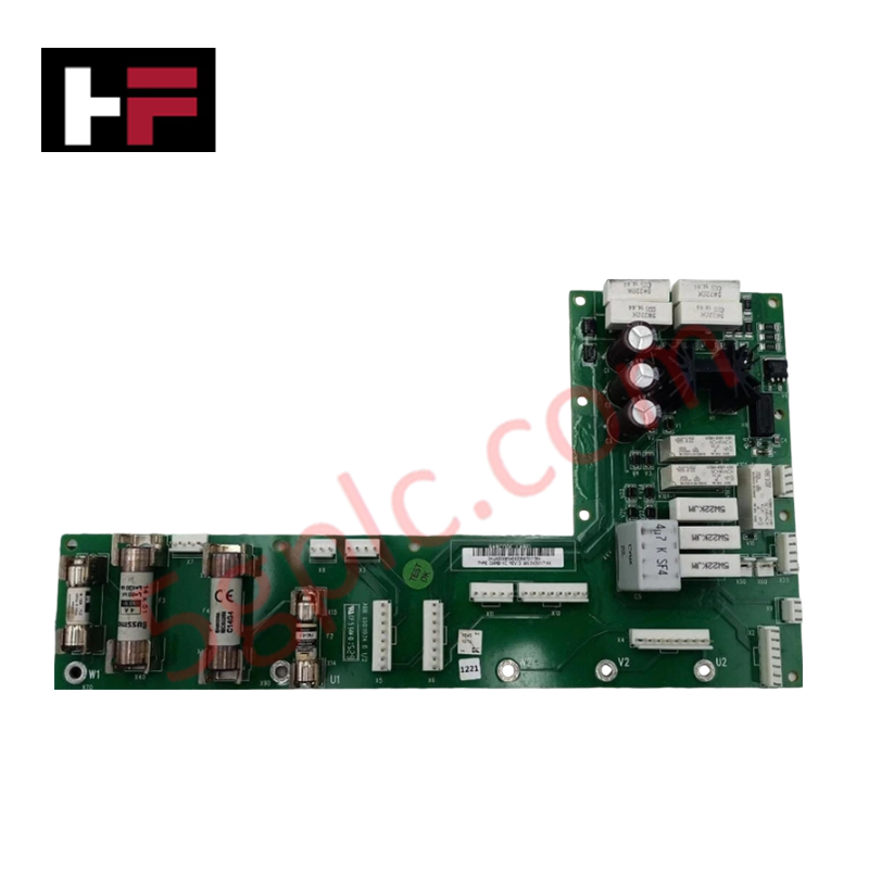
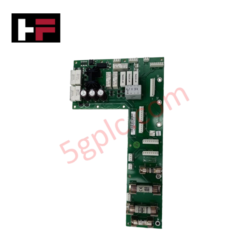
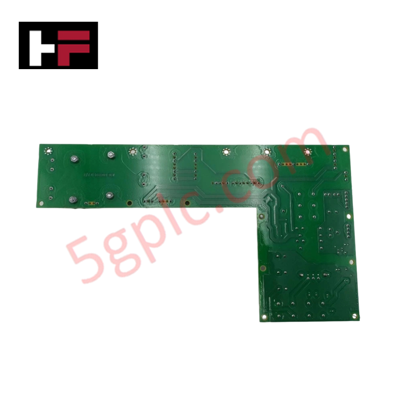
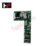
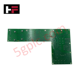
The ABB CMRB11C REV D, also cataloged as the CMRB11C Micro Control Interface Board, operates as a dedicated hardware component for micro control interfacing and load switching within ABB industrial automation networks.
Hardware Specifications
| Parameter | Specification |
| Model | CMRB11C REV D (Product ID: 3AUA0000054682D) |
| Brand | ABB |
| Origin | Finland / Switzerland |
| Weight | 0.35 kg (Standard assembly baseline) |
| Dimensions | 77 mm x 22.5 mm x 114 mm |
| Operating Temp | -20 to +55 deg C |
| Power Consumption | Dependent on active relay coils and execution states |
| Input Voltage | 24 VAC/DC, 50/60 Hz |
| Output Load | 15 A, 250 VAC |
| Connection Type | Screw terminal |
| Mounting Type | Panel-mounted |
| Storage Temperature | -40 to +70 deg C |
Profinet / EtherNet/IP Deterministic Networks and Timing
The interface card layer structures are optimized to synchronize physical relay switching states with host processor logic execution over Profinet / EtherNet/IP deterministic networks. The internal transceiver modules map field input and output data across the shared control matrix without degrading backplane bus communication velocity. Circuit tracking geometry guarantees consistent isolation and timing profiles between the low-voltage 24 VAC/DC coil excitation logic and the high-capacity 15 A, 250 VAC contact paths, maintaining absolute firmware flash compatibility with the primary controller framework.
Frequently Asked Questions
Q: What are the installation restrictions concerning the 15 A output load parameters?
A: The 15 A rating applies up to 250 VAC under resistive load profiles. Inductive loads with high inrush metrics require external surge suppression or suppression diodes across the screw terminal nodes to prevent contact erosion.
Q: How is the input frequency managed when running the logic on a 24 VAC supply?
A: The onboard input filtering accommodates both 50 Hz and 60 Hz frequencies, converting the AC sinusoidal signal internally into a stable DC plane for the micro control circuits.
Q: Does the module support direct hot-swap extraction while under a 15 A load?
A: No. Physical disconnection while carrying a 15 A, 250 VAC current load will cause electrical arcing at the screw terminal interface, resulting in terminal degradation and potential backplane voltage glitches.
Field Installation Guidelines
-
Panel-Mounted Alignment: Affix the module securely to the backplate using specified mounting screws. Verify the physical dimensions (77 mm x 22.5 mm x 114 mm) fit the panel layout constraints before torque execution.
-
Terminal Torquing Spec: Field wiring must be secured via the integrated screw terminals. Ensure wire insulation is stripped uniformly and screws are tightened to the factory rating to prevent contact resistance variations.
-
Power Cable Segregation: Route the 250 VAC output load conductors away from the low-power 24 VAC/DC control lines inside the cabinet wiring ducts to eliminate inductive noise cross-talk.
-
Thermal Margin Safety: Maintain standard vertical distance clear of heat-producing components to allow steady airflow across the -20 to +55 deg C operating temperature window.
Additional Information
- 100% Genuine Parts: All products are original and authentic, ensuring reliable industrial performance.
- 30-Day Refund Guarantee: Return any in-stock item within 30 days in original, unopened packaging for a full refund (excluding shipping and fees).
- 12-Month Warranty: Covers defects in materials or workmanship; excludes misuse, normal wear, or unauthorized modifications.
- Worldwide Shipping: We ship via USPS, UPS, FedEx, and DHL. Delivery times vary by country and may be subject to customs or import fees.
- Support & Contact: Technical and warranty assistance is available anytime. Contact us here: Contact.
- Purchase Guidance: Check product specifications and compatibility carefully before ordering to ensure proper application.









Tech & Buying Guide

Mastering the Siemens PLC Scan Cycle: How the CPU Executes Automation Programs
Industrial automation relies heavily on programmable logic controllers (PLCs) to manage complex manufacturing processes. Many engineers dive straight into programming without mastering the underlying architecture. However, understanding how a PLC CPU executes a program ensures reliable system design. Therefore, mastering the scan cycle optimizes both performance and troubleshooting in modern control systems.

How to Connect to Siemens S7 PLCs: 5 Essential Communication Methods
Establishing a reliable hardware link between a programming terminal and a Siemens SIMATIC controller is essential for engineering workflows. Field engineers rely on distinct physical layers, ranging from legacy serial connections to high-speed Industrial Ethernet protocols. Modern factory automation environments prioritize fast data transfer and seamless driver integration. Selecting the correct connection method simplifies program downloads, online monitoring, and system troubleshooting in complex control systems.

Will PLCs Become Obsolete? The Future of Control Systems in Industry 4.0
Modern manufacturing is undergoing a rapid technological transformation driven by Industry 4.0 innovations. Technologies like Artificial Intelligence (AI), Machine Learning (ML), and the Industrial Internet of Things (IIoT) are dominating discussions across the factory automation sector. Consequently, many engineers wonder if these advanced digital tools will eventually replace traditional Programmable Logic Controllers (PLCs). However, evaluating the core physics of industrial operations reveals a very different reality for control systems.